 Part 1 of this article, which ran in the February 1999 issue of Sensors, explored the physics of vibration; dynamics of a spring mass system; damping; displacement; velocity; acceleration; and the operating principles of the sensors that detect and measure these properties. Part 2, in the March issue, addressed the ways in which sensor performance is affected by fundamental accelerometer characteristics and the operating environment. The figures and references in Part 3 are numbered consecutively from Parts 1 and 2.
A more detailed version of the material presented here is scheduled for publication by the Institute of Environmental Sciences and Technology (IEST) as reference work IEST-RP-DTE011, Transducer Selection [15]. The document may be purchased from the organization by contacting the Institute of Environmental Sciences and Technology, 940 E. Northwest Hwy., Mount Prospect, Illinois 60056, 847-255-1561, fax 847-255-1699, [email protected] or www.iest.org
Transducer Installation
To achieve accurate measurements, the motion of the test structure must be accurately transmitted to the accelerometer. The mounting method, hardware, and location are therefore as important as transducer selection. The wisest course is to use the same mounting method for operation as was used for calibration. If for some reason a different technique must be substituted, it must be characterized for its dynamic characteristics over the intended frequency and amplitude range.
Surface Preparation. The transducer mounting technique and surface conditions can affect the amplitude-frequency response of the measurement, particularly at high frequencies (see Figure 18). A flush mounting with a smooth, flat surface is essential. The mounting surfaces and tapped holes should conform to these specifications, which are easily achieved by following good machine shop practices:
Surface flatness 0.0003 in. TIR
Surface roughness 32 µin.rms
Perpendicularity of hole 16 min.
Tap class 2
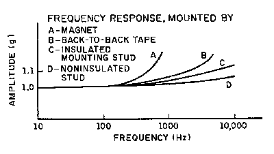 |
| Figure 18. Transducer measurement accuracy can be influenced by the technique used to mount the sensor. Performance is plotted here for the four most common mounting methods. |
A thin layer of a light lubricant or acoustic couplant will improve transmissibility by filling voids with nearly incompressible fluid and thereby increasing the compressive stiffness of the joint. This enhancement is particularly important for measurements above 1000 Hz, where changes in resonance have a significant effect on measurements.
Stud Mounting.
This technique provides higher transmissibility than other methods. The transducer should be mounted with the appropriate adapter studs or bushings, ensuring that the entire base of the transducer has good contact with the surface of the test article. These studs are the correct length and incorporate a flange to prevent "bottoming" of the screw in the accelerometers. Use a torque wrench to ensure repeatability in transducer installation and prevent damage by over-torquing. The mounting torque recommended by the manufacturers should always be followed.
Adhesive Mounting. Most miniature accelerometers can be mounted using only an adhesive. Whether used to mount the accelerometer directly to the test structure or to an adapter block, or to mount the block to the test structure, the adhesive becomes part of the structure being measured. The stiffness of the cured adhesive is critical to total system measurement performance. No adhesive is as stiff as a mounting stud, however, and the more adhesive joints between the test structure and the accelerometer, the greater the degradation of transmissibility. The manufacturer's frequency response and linearity data should be representative of performance with the recommended adhesive. Alternative adhesives should be evaluated over the intended frequency and amplitude range.
Dismounting an adhesively mounted transducer deserves comment. It should not be hammered off; instead, use appropriate solvents and a light shearing torque to remove both the sensor and all traces of the adhesive. Never use a knife or file lest you nick or scratch the mounting surface. The manufacturer can probably supply a removal tool if you need one.
Magnetic Mounting. Magnetic mounting adapters are popular for applications requiring periodic quick point-to-point measurements. Most magnetic adapters are massive, and useful only for measurements below a few hundred hertz. Ask the manufacturer for information on the transfer characteristics of the magnetic adapter before you use it. The magnetic force attracting the adapter/accelerometer assembly toward the mounting structure can deliver several thousand g's of shock to the sensor and cause premature failure, so be careful when you handle such assemblies.
Triaxial Mounting Block. Mounting blocks, or adapter blocks, should be used only when absolutely necessary. Because they constitute a dynamic structure between the accelerometer and the surface it is to measure, they limit the usable frequency response. They act as an additional spring mass system whose transfer function must be known and compensated to accurately interpret the accelerometer output. Always remember that it is the motion of the mounting block that you are measuring, which might not accurately represent the motion of the test structure's surface.
Many installations nonetheless require an adapter block for triaxial measurement, improved transmissibility from a curved or irregularly shaped surface, minimal modification or damage to the test item, or simply the use of standardized mounting hardware. The mounting block, as a part of the structure being measured, must be kept as small, lightweight, and stiff as possible. Beryllium is the ideal mounting material, but it is expensive and hard to machine, and the dust from machining is toxic. Most blocks are therefore made of a magnesium alloy. When weight is not a factor (e.g., for mounting directly to the armature of a vibration exciter), you should consider less expensive aluminum alloys. The dynamic characteristics of most metals other than beryllium are very similar, so selection is usually based on mass, cost, and convenience. The accelerometer should be calibrated on the block, over the intended frequency and amplitude ranges and simulating actual conditions as nearly as possible.
Isolation Adapters. Electrically isolated and adhesive mounting adapters may be helpful in some applications. If you are using an isolated mounting stud/adapter, make sure that the couplant between the transducer and the isolation stud is nonconductive. In any case, safe mounting practices dictate that couplants should not be allowed to creep across the insulating layer. Accelerometer manufacturers should be able to provide dynamic characteristics of their adapters with the intended accelerometers.
Location. At modal resonance frequencies, local motion can vary tremendously over very small distances. Nodes and antinodes may be very close together. A dynamic analysis of the structure to be monitored, either by actual measurement or by computer modeling, will allow you to estimate the most appropriate accelerometer locations. Whether dynamic analysis is available or not, the mounting location should be determined by the purpose(s) of the measurement(s). No single site is likely to be representative of the whole body (or rigid body) motion of the structure. Furthermore, on realistically complex structures no two locations are likely to exhibit identical motion over a wide frequency range (see Figure 19).
| Figure 19. When choosing a mounting site for your accelerometer, keep in mind that complex structures will exhibit different deformations at different locations. If dynamic analysis is available, use it. | 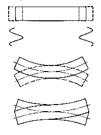 |
Transducer Recalibration
Transducer calibration consists of measuring the electrical output generated by a known mechanical input. Accelerometers for use in vibration measurement should be calibrated with vibration input; those for shocks >100 g should be calibrated with a shock input. For vibration, this is most accurately done with either the reciprocity method or a laser interferometric technique (see Figure 20). For shock, the best accuracy is obtained with the direct comparison method up to ~10,000 g and a Hopkinson bar shock calibrator for higher levels. These highly accurate methods provide estimated uncertainties of 0.5% at 100 Hz at a few g's (NIST) to ~6% at 100,000 g (with a Hopkinson bar) [12].
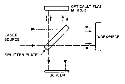 |
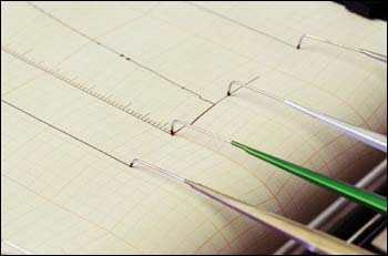
| Figure 20. Calibrate your accelerometer by subjecting it to the physical property it is intended to measure. If it is vibration, consider the well-accepted laser interferometric technique. |
A more practical, if less accurate, recalibration technique for vibration sensors is direct comparison ("back-to-back"), in which a specially designed reference standard is used to make a direct comparison with the unit under test. For greatest accuracy and widest frequency range, the reference standard may be built into the armature of a calibration shaker.
Calibration should be performed over at least the frequency and amplitude range to be measured; with the accelerometer mounted as it will be in service; and under the same temperature conditions. Calibrations should always be traceable to NIST (in the U.S.) or a recognized national standards agency.
Recalibration of sensitivity and frequency response should be performed at regular intervals, whose selection entails a tradeoff between the cost of calibration and the cost of measurement uncertainty. If it is known that the accelerometer has not been used beyond its rated specifications, and if prior recalibrations show that the sensitivity values are stable and remain within specification, recalibrations typically need be performed only at regular intervals not exceeding 12 months. Most standard transducers, for instance, show no discernible changes over five years or more. If a performance parameter changes to a degree outside defined tolerances between recalibrations, the interval should be shortened and significant deviations should be reported (see Figure 21, below).
|
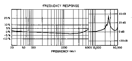
| Figure 21. Calibration data are typically plotted as shown here. Keeping track of this information will help you establish a calibration cycle that reflects the stability of your sensor's performance parameters. RESONANCE FREQUENCY: 25,627 Hz CAPACITANCE AT 100 Hz: 6631 PF |
If the accelerometer is used in severe environments, particularly those associated with shock testing, it may be prudent to use shorter recalibration intervals until sufficient history has been established to justify a longer interval. It is advisable that accelerometers used in shock testing (other than pyroshock) be recalibrated at intervals not exceeding six months; sensors used in pyroshock testing should recalibrated every three months. Where the pyroshock tests are expected to generate shock pulse amplitudes close to the accelerometers' maximum rating (particularly with frequency components near the natural frequency), it is a good idea to perform pretest and post-test calibrations for each use.
Caution: The shock levels in violent tests are commonly described in terms of heavily filtered data, so potentially damaging amplitudes at high frequencies may not be reflected in the predictions.
Transducer Selection by Application
High-Frequency Measurement. Gear noise analysis, turbine or rotating machinery monitoring, and other high-frequency signature analyses require accelerometers with exceptional high-frequency characteristics:
- Resonance Frequency. The resonance frequency must be high enough to provide adequate bandwidth. High-frequency harmonics may excite the resonance of the sensor if it is too low for the application.
- Mounting Method. Stud mounting is the only acceptable method. Couplant should be used whenever possible.
- Calibration. Frequency response calibration above 10 kHz is essential for this type of accelerometer. The impulse method for high-frequency calibration is acceptable if the input impulses are well defined.
Certain piezoelectric/integral electronics piezoelectric (IEPE) accelerometers with very high (>70 kHz) resonance will satisfy these requirements. For very high frequency measurement, piezoresistive accelerometers are available that have >1 MHz resonance, but they also have very low sensitivity. High-frequency dynamic force measurement is not common, although there is no technical reason it cannot be measured using standard piezoelectric or IEPE force sensors.
Low-Frequency Measurement. Applications such as modal analysis, seismic measurement, and transportation monitoring require accelerometers with exceptional low-frequency characteristics:
- Low-End Frequency Response. For very low frequency measurements (near DC), DC-coupled devices such as piezoresistive, variable capacitance (VC), or servo are the natural choices. For motion studies of test objects where velocity and displacement data are to be derived from the acceleration signals, it is imperative to use accelerometers with DC response. AC-coupled devices such as piezoelectric or IEPE accelerometers cannot accurately follow long-duration pulses, and the errors may be magnified during the numerical integration processes. For measurements from a few hertz and up, AC-coupled devices with sufficient low-end response may be used.
- Base Strain Sensitivity. Base strain sensitivity cannot easily be distinguished from vibration signals, especially at low frequencies where the displacement amplitude is large. The accelerometer should have very low strain sensitivity. Adhesive mounting can reduce this problem to a large degree if the application allows.
- Thermal Transient Sensitivity. Because thermal transient outputs are low-frequency phenomena, they have significant effects on low-frequency measurements. Thermal protective boots may reduce the problem.
- Low-Pass Filtering. In many applications where the desired information is in the low frequencies, high-level, high-frequency components may reduce the usable dynamic range of the system. An external or internal low-pass filter may solve the problem.
 All piezoresistive, VC, and servo devices have DC response, but servo types tend to be big and heavy. Piezoelectric/IEPE accelerometers with flat response down to 1 Hz can be used for most modal analysis applications. IEPE force sensors are commonly used for modal analysis to measure the input forcing functions from electrodynamic shakers or impact hammers. Most force sensors are designed to have a very long time constant and hence very good low-frequency response.
Shock Measurement. Package drop-test, auto crash test, pyroshock/simulation, and similar applications require accelerometers with special capabilities. For high-g shock in particular, where things are nonlinear and difficult to characterize, choosing the right accelerometers can be critical [17]. The basic accelerometer selection considerations are:
- Zero Shift. Zero shift or DC offset, a sudden change of baseline level during a high-g event, is a type of error usually associated with but not limited to piezoelectric/ IEPE accelerometers [1]. Because there is no universal standard for this parameter, it cannot be found in manufacturers' specifications. In theory, piezoresistive devices designed for high-g shock do not have this problem.
- Survivability. Most accelerometers can survive low-g shocks without suffering internal damage. In high-g tests, however, sensor breakage is fairly common. One solution is to overestimate the maximum shock level when selecting the range of a shock accelerometer. In general, the closer the sensor is to the source (explosive or impact), the higher the input g level. Piezoelectric/IEPE accelerometers tend to be more rugged than other types; some VC devices have reportedly survived up to 20,000 g.
- Range. The usable output range should not be confused with survivability. An accelerometer may have to measure only 100 g F.S., but might be required to survive an initial shock of 10,000 g preceding the low-level event. Another distinction should be made between the maximum expected level from a shock response spectrum and the actual input spectrum the accelerometer is likely to experience.
- Low-Pass Filtering. Low-pass filters can be used at the input of an amplifier to prevent an overload condition due to unexpected input spikes.
- DC Response. When measuring long-duration shock, you might need accelerometers with DC response to capture low-frequency data. If the data are be integrated to yield useful velocity or displacement information, DC response is an absolute necessity.
Sensor selection for low-g shock applications is fairly straightforward once the survivability and frequency response issues have been settled. For high-g applications, there are various types of piezoelectric/
IEPE accelerometers rated to >50,000 g; some have built-in electrical and/or mechanical filtering to prevent zero shift problems. Piezoresistive and VC accelerometers offer DC response, an important consideration in certain applications.
Micro-g Measurement. Measuring vibration on the Hubbell telescope or noise in a nuclear submarine under the ocean requires an extremely sensitive accelerometer with an exceptional noise floor and dynamic range:
- Signal-to-Noise Ratio (SNR). High sensitivity and low noise floor are key to micro-g vibration measurement. High sensitivity and a good SNR, however, may come at the expense of size and weight.
- Environmental Sensitivities. Because all extremely high output transducers can be affected by environmental factors such as base strain, thermal transient, and acoustic interference, you should use some form of environmental barrier with a micro-g sensor.
Several piezoelectric/IEPE, VC, and servo accelerometers have been designed specifically for low-g measurement. These devices vary significantly in price, size, and weight. High-sensitivity PR accelerometers are usually more fragile and have lower outputs than competing types and may not be suitable for this type of application.
High-Temperature Environment. Shock and vibration testing of jet engine propulsion systems and power generators requires transducers that can withstand a high-temperature environment:
- Survivability. The accelerometer must survive and operate at temperatures >=400ºC without degradation in sensitivity or resonance characteristics.
- Temperature Response. A transducer's performance at its temperature limits must be well defined. Is the sensitivity at these temperatures repeatable and predictable? Is the output sensitivity compensated for temperature effects? Some piezoelectric transducers show a drastic drop in internal resistance at high temperatures, rendering the signal conditioner (charge amplifier) inoperable.
- Cable Survivability. Can the connector and cable assemblies survive the hot environment? The output cable must have a temperature rating similar to the transducer's. Most high-temperature cables use ceramics as their dielectric, with the result that they are often brittle and inflexible. Piezoelectric transducers are the only type known to survive high temperatures, with some rated up to 750ºC. Each of the various crystal materials used in making these sensors has advantages and tradeoffs.
Low-Temperature Environment. Measurements performed near cryogenic conditions, such as the cooling system on rocket engines or spacecraft components, require transducers that can operate at temperatures as low as 250ºC:
- Temperature Response. The sensitivity of many transducer designs drops off dramatically when approaching absolute zero. Consult the manufacturer for test data at these temperatures.
- Thermal Transient Sensitivity. Small temperature changes at near absolute zero can be considered thermal shock for the sensing element. How does the accelerometer respond under these conditions? The manufacturer should be able to provide the pertinent specifications and calibration data.
- Survivability. Components inside the transducer are required not only to operate at near absolute zero temperature without disintegrating, but also to survive multiple cycles of thermal shock. Multiple cycles of thermal shock due to thermal expansion can cause reliability problems in microelectronic circuits (chip and wire or surface mounted types). Transducer designs without internal electronics have proved to be more reliable under these conditions.
- Cable Survivability. Most cables become very brittle at cryogenic temperatures. How long can the cable operate before signal degradation takes place? Careful selection of the right cable type is critical.
Radioactive Environment. Measurements performed near radioactive sources, such as a nuclear reactor and its pump system, require nuclear-hardened transducers. The level of radioactivity varies according to the measurement location. 
- RAD Rating. Is the transducer rated for the intended environment? Has the design been used in nuclear applications? The manufacturer should be able to supply where-used and qualification information on request.
- Cable Survivability. Most cable materials, among them the common Teflon dielectric, fail after long-term exposure to radioactivity. Cable assemblies for nuclear application must have properties suitable for extended use.
- Sensitivity Stability. What are the long-term effects of high doses of radioactivity on transducer sensitivity? Sensitivity should remain stable and within the tolerance range specified by the manufacturer.
Several manufacturers offer piezoelectric transducers, the preferred accelerometers for use in nuclear environments, with RAD ratings up to 1010 integrated gamma flux.
Industrial Environment. Vibration measurements performed in an industrial environment differ from those in a laboratory. Many applications require that the transducer have certifications for intrinsic safety. 
- Ruggedness. The physical conditions inside a manufacturing plant necessitate a rugged transducer design. Cable connector, cable, and mounting should be able to withstand normal day-to-day use.
- Hermetic Sealing. Many industrial environments are characterized by moisture and other liquid contaminants. A hermetically sealed design will keep the sensor in proper operating condition for an extended period of time.
- Low Cost. Although not a technical consideration, the price of the accelerometer can be an important factor in industrial applications where hundreds of sensors are being used at one time.
Many piezoelectric/IEPE transducers have been designed specifically for industrial applications, although low-impedance types are more widely used due to their apparent advantages in dirty environments. Other sensor types are less popular in this area, primarily due to their higher cost.
High Acoustic Intensity Environment. Applications entailing high-level vibration can generate a high acoustic field near the transducer. On a rocket motor, for example, the accelerometer can be bombarded with sound pressure levels as high as 120 dB:
- Acoustic Sensitivity. Even though low acoustic sensitivity is naturally desirable for this type of environment, it is not a parameter that manufacturers normally publish. You must ask specifically for this information.
- Small Size. Transducers with smaller surface areas generally have lower acoustic sensitivity. Some form of barrier, such as a rubber boot, may reduce the sensitivity even further.
All transducers show some degree of sensitivity to high-intensity acoustic input. Consult different manufacturers before making your final selection.
Ministructure Measurement. In many applications the test articles are no bigger than a tennis ball. Making shock and vibration measurements under such conditions requires sensors with unique characteristics:
- Mass-Loading Effect. Mass loading can change the dynamic responses of the measurement. The accelerometer's size and weight must not be disproportionate to the test article--no greater than 10:1 is the general rule, but since the rule refers to dynamic mass, it must be used judiciously.
- Mounting Method. Because it is impractical to drill threaded holes in a small test article to accommodate stud mount type sensors, give careful consideration to adhesive mounting--and scrupulously follow the manufacturer's mounting/removal instructions.
- Resonance. Small structures usually have high-frequency modes. Accelerometers with higher resonance (>50 kHz) may be required.
- Cable. When the test structure is very small and lightweight, even the stiffness of the cable can affect the dynamic responses. Small-gauge, flexible cable should be used in these situations.
There are piezoelectric/IEPE and piezoresistive accelerometers on the market that are very small and light (0.14 gram) that help minimize mass-loading problems. The larger sizes of servo types make them unsuitable for mini-structure measurements.
Signal Conditioning
As noted earlier, signal conditioning must be matched to the transducer type. Strain gauge and piezoresistive transducers can be conditioned with strain gauge amplifiers or bridge conditioners. All you need to be aware of is the bridge configuration being used. Most modern piezoresistive accelerometers are full-bridge construction. VC types usually have integral signal conditioners and need only a reasonably constant voltage within a wide voltage range.
Piezoelectric accelerometers usually require a charge amplifier but can sometimes be used with a high input impedance voltage amplifier (op amp). In some applications, piezoelectric accelerometers are equipped with remote charge converters, or preamplifiers. These can provide a preamplified low-output impedance signal for electrically noisy environments or installations where the signal leads must be run through bulkhead connectors. IEPE devices require a special coupler or signal conditioner that includes a constant-current power source and a coupling capacitor (see Figure 22).
x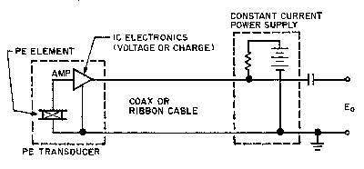 x x |
| Figure 22. IEPE sensors require a special coupler or signal conditioner incorporating a constant current power source and a coupling capacitor. |
Downstream of the input stage, all vibration signal conditioners tend to be similar, typically containing additional amplifier stages for ranging, filters, and perhaps integrators or differentiators. Modern data acquisition and vibration control systems usually require anti-alias filtering and A/D conversion to condition the signal for digital recording and/or processing.
System Considerations
Cabling and connectors are often responsible for large errors or high noise levels, especially with piezoelectric accelerometers. With long cable runs between accelerometer and signal conditioner, cable capacitance can form a low-pass filter that attenuates high-frequency data. Long high-impedance cables carrying low-level signals are especially susceptible to environmental electromagnetic and capacitively coupled noise.
The vibration measurement system is best designed "backward," beginning with system requirements and considerations and then selecting components to make up the system. These system considerations and requirements will include all of the above-mentioned, in addition to the accuracy required, the purpose for which the measurement is being made, the form the data need to take and the way they will be displayed or recorded, and the instruments or measurement systems that are readily and economically available.
References
1. A. Chu. "Zero Shift of Piezoelectric Accelerometers in Pyroshock Measurements," Endevco TP 293.
12. R. Sill. "Minimizing Measurement Uncertainty in Calibration and Use of Accelerometers," Endevco TP 299.
15. A. Chu. 1998. Measurement Transducer Selection, Institute of Environmental Sciences and Technology Recommended Practice IEST-RP-DTE011, Institute of Environmental Sciences and Technology, Mount Prospect, IL.
17. H. Himelblau and A. Piersol. 1994. Handbook for Dynamic Data Acquisition and Analysis, Institute of Environmental Sciences, IEST RP-DTE012.1. *
