
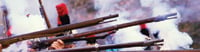
The development and proof testing of many types of medium-caliber ammunition entails measuring the round's performance while it is moving inside the gun barrel. These in-barrel events—propagation of the propellant pressure wave, acceleration, balloting, spin, and electronic functions—occur at very high speeds. (Balloting refers to off-boresight movement of a round in a gun, typically due to gas leakage around the ammunition and the elasticity of both barrel and round under the high pressures associated with firing.) RF-based telemetry techniques do not work well inside a gun's metal barrel. An onboard recorder (OBR) is the only way to collect the desired performance data.
 |
While large OBRs have been used to obtain data on larger rounds [1], it is not a trivial matter to pack the necessary functions into a volume small enough to fit inside medium-caliber ammunition such as a 25 mm round. Controlex has accomplished this with the CM346 miniature solid-state recorder (see Figure 1).
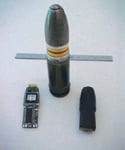 Figure 1. From left to right are the bare printed wiring assembly, a 25 mm host round, and the encapsulated recorder ready for placement in the round. |
Other Technical Challenges
The short time that the fired round is in the barrel, accelerating from rest to supersonic speeds in a few milliseconds, creates very short transient events with durations of a few milliseconds and rise times in the microseconds. Capturing sensor waveforms with good fidelity demands a very fast sampling rate.
The rapid acceleration of the fired round imposes very high g-forces on the recorder riding in the round. These forces can reach 100,000 g for a short duration, so the recorder's mechanical design must provide considerable structural integrity.
The small space allotted to the data recorder leaves no room for a battery. The Flash memory devices often incorporated in OBRs typically do not write fast enough to meet the bandwidth necessary for capturing the fast signals generated by medium-caliber ordnance. So a nonvolatile memory device capable of writing at a minimum of 1 mHz is needed to handle the recorded data for subsquent analysis.
Design Considerations
Perhaps the most important design decision is the use of ferroelectric RAM (FRAM) to store the sampled data. FRAMs, now commercially available, use a layer of ferroelectric ceramic film with a square D-E loop as the storage element for each memory cell of the chip. Storage is accomplished by retention of polarization charge in the film, with one unique state for 1's and another for 0's. In contrast to Flash devices, which have endurances of 105 cycles and require careful management of memory use, FRAMs exhibit endurance of more than 1010 cycles, far in excess of the recorder's expected life. FRAM devices can operate at 5 mHz read and write cycles, fast enough to support 1 mHz sampling. Further, compared to Flash, FRAMs do not require erasing to a known state before writing new data. Their interface is quite like a conventional static RAM, greatly simplifying system design.
To provide power normally supplied by a battery, the recorder runs on energy stored in a capacitor to drive DC/DC converters that deliver regulated supply voltages. Charging the capacitor with a power supply external to the recorder right before a test round is fired gives it enough energy to run the recorder for the duration of the bullet's travel through the barrel. An important design requirement for the converters is that they deliver regulated output voltage even as the voltage on the capacitor falls when the charge is removed.
Encapsulating the printed wiring assembly (PWA) in a molded shape that fits securely in the body of the host round (see Figure 2) ensures that no component on the PWA moves relative to another, essentially creating a monolithic block that can withstand shocks >100,000 g. Moreover, the recorder not only survives but can be reused, dramatically reducing cost of ownership.
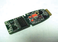 Figure 2. The recorder is incorporated into a single printed wiring assembly (PWA). The connection path to the reader is at the top of the PWA. Note that all components and I/C are surface-mounted COTS parts. |
Little room is available to include support circuitry for reading the contents of the recorder following a shoot. An external reader was therefore developed, operating under Windows and allowing easy downloading of recorded test data in an ASCII format to a PC for archiving and later analysis. The reader is mated to the recorder via an edge connector that engages gold-plated "lands" at the recorder's upper end. Note that no connections are made when in the test round, so the connectors are not required to survive high shock levels. In addition to downloading recorded data, the reader serves to perform confidence testing on the recorder by writing and reading a sequence of patterns in it.
Figure 3 is a block diagram of the recorder. Volume constrictions allowed the inclusion of only one channel. Sensor signals are fed to an instrumentation amplifier offering very high (>100 dB) common-mode rejection and providing the balanced inputs that bridge-type sensors require. An analog bandwidth of 0.35 MHz and a rise time of 1 μs preserve the fast sensor signals expected. The amplifier gain may be user-set by a single chip resistor. The gain and therefore the scale factor may be set from ±1 mV to ±1 V F.S. The amplifier's inherently wide bandwidth easily supports the 350 kHz bandwidth at the highest gain.
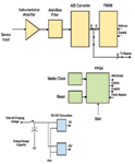 Figure 3. This block diagram shows the major elements of the CM346 recorder. They all fit inside a very small 25 mm ammunition round. |
Following the amplifier, the analog sensor signal drives a low-pass switched capacitor filter with a linear phase response. The purpose is to provide good transient response and minimize the distortion of fast signals. The filter serves to eliminate aliasing.
The A/D converter's 8-bit resolution provides a precision of better than 1% for a bidirectional sensor signal. Its digital output drives the data lines of a FRAM whose addresses are incremented in synchronism with the sampling rate. Because a recording time of only a few milliseconds is needed, a FRAM with a capacity of 8 × 8 K serves the purpose and allows 8 ms of recording at a rate of 1 mHz. Higher capacity FRAMs are available for longer recording times. The FRAM's multiplexed data port allows connection to an external reader to recover test data. Its inherent nonvolatility causes data to be retained in the absence of power, making for convenient recovery of the test round, removal of the recorder, and later downloading of the test data in the laboratory.
 |
A silicon oscillator serves as the master clock. This device delivers a stable clock frequency even while experiencing extreme shock. An FPGA generates all clocks, control terms, and addresses to the FRAM. It also handles reader commands when in the read mode.
To allow 1% regulated supply rails, important for accurate handling of analog signals, DC/DC converters connected in a SEPIC topology and operating at 1.4 mHz are used. Their inputs are supplied from a storage capacitor and they maintain regulation in face of 2:1 variation of capacitor voltage as it discharges. Fast switching speed allows the use of very small inductors.
Summary
A practical solid-state recorder small enough to fit inside medium-caliber ammunition has been designed, built, and demonstrated. The architecture easily allows for variations to meet differing requirements.
Bruce Kaufman is President, Controlex Corp., Van Nuys, CA; 818-780-8877, [email protected].
Reference
1. Bruce Kaufman, "A Nonvolatile Solid-State Recorder for 100,000 g Environments," Sensors, Vol. 17, No. 6, June 2000, pp. 46–51.
Acknowledgments
The author is pleased to acknowledge the superb design talent of Jules Canel and the support of General Dynamics Corp.