

The Fashionable IoT
The Internet of Things (IoT) device market, comprised of intelligent, connected electronics spanning smartphones to wearables, and even household appliances, continues to experience exponential growth year-over-year. Often intended to be worn or, like smart ovens and refrigerators, to contribute to the aesthetics of the space in which they function, IoT devices tend to be more personal than many electronics have historically been. As such, IoT electronics are generally expected to be user-friendly, aesthetically pleasing, and as sleek and subtle as possible.
In light of this, electronic engineers who design IoT devices are continually challenged to make them ever smaller and more cost-effective while retaining all of their current capabilities, and frequently incorporating additional ones as well. To satisfy these size, cost, and performance constraints, engineers must typically reduce the size of both its PCB and board-level components, and employ creative space management strategies.
Making The Right Connections
Connectors can play a crucial role, in achieving a design's size, cost, and performance constraints. Therefore it's critical for engineers to have a basic understanding of some of the most reliable and historically proven contact systems available when designing IoT devices, and especially the portable or wearable ones, as these tend to be the among the most compact.
The measure of a connector's ruggedness and reliability is all but solely reliant upon its contact system, as is squarely evidenced by the insulator-less connectors that have increasingly spread throughout the commercial, industrial, medical, and transportation markets over the past six years. Introduced to market in 2010 as STRIPT contacts, this broad range of single contacts was developed to function exactly like traditional connectors, but without an insulator, which drastically reduced both size and cost (see figure 1). These novel insulator-less connectors are now available in several different contact technologies, and other suppliers have recently introduced their own versions as well.
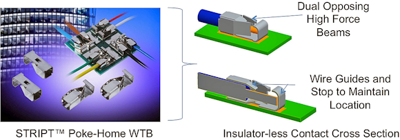
Fig. 1: Released to market in 2010, the 9296 Series poke-home STRIPT contacts were the industry's first insulator-less contacts. This technology has since evolved to encompass several other contact technologies due to their proven ability to provide rugged, reliable connections equivalent to traditional connectors, but with significant size and cost savings.
Internal board-to-board and external pluggable module connectors are often challenged to provide more than just signal and power connections, and can quickly become the critical path in high shock or vibration environments, the weakest component in extreme cycle-life applications, or the savior at the production line assembly or the end-user interface point. In these applications, the most reliable and forgiving contact is a properly designed compression beam mated to an opposing pad.
Next page
Go For The Gold
Although compression contacts can be made from any of many material choices, gold-plated beryllium copper (BeCu) is best suited for meeting these particular environmental, mechanical, and performance needs. BeCu has been proven to offer the highest deflection range and fatigue resistance of all the alloys on the market, and the gold plating both enhances the contact's conduction capabilities and, by virtue of being extremely nonreactive, preserves the quality of the connection over time.
However, to effectively maintain the electrical connection up to the maximum limits of such applications, engineers must still ensure that the thickness and geometry of the BeCu contacts has been designed to provide sufficient contact force throughout the entire deflection range. This contact force can vary from 25 gram-force (gf) to more than 200 gf depending on the specified temperature and shock and vibration requirements, and deflection ranges vary based on the size of the connector and final compressed height, but typically span between 0.5 mm and 1.0mm. Consequently, gold-plated BeCu contacts designed to provide a large contact deflection range can absorb excessive plastics and housing tolerances, making them very assembly friendly.
One of the most unique aspects of compression contacts is their deflection process. When a compression contact deflects, the beam actually slides across the pad surface, wiping it clean of any oxides that may have gathered and allowing it to consistently deliver the best possible connection, even after thousands of cycles.
Introduced to market approximately 25 years ago, compression contact technology has evolved to include several distinct styles (see figure 2), each of which were initially developed to solve the specific needs of a single application and later morphed into a range of off-the-shelf products aimed at solving similar design challenges in related applications.
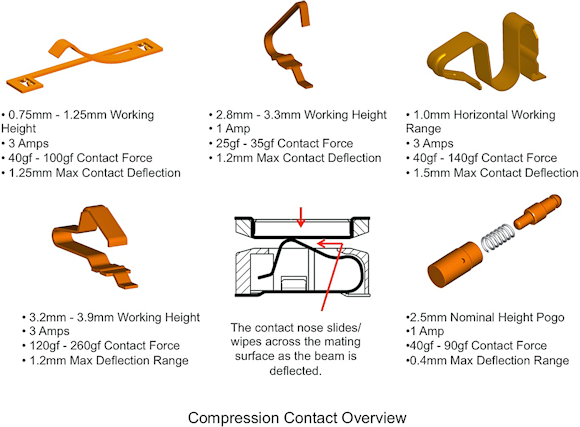
Fig, 2: An overview of the various compression contact technologies currently available.
The latest addition to this lineup, STRIPT pogo pin compression contacts, was introduced in 2014. Firmly situated at the extreme end of the durability range with 10,000+ mating cycles, insulator-less pogo pin contacts allow for the design engineers to select individual stacking heights, PCB placement location, and pitch configurations, rather than adapting their designs to specific connector arrangements, and are especially ideal for docking applications.
Next page
Ensure The Sensor Is Secure
Selecting connecters to secure sensors and other leaded devices to PCBs isn't generally as challenging as selecting the right compression connectors. However, the basic principles, i.e., evaluating contact materials and geometries to ensure they can satisfy the environmental, mechanical, and performance needs of a particular application, are essentially the same.
In most applications, it's fairly easy to select the larger, higher pin-count and system level connectors, as these tend to be defined by various industry standard organizations. The challenge typically arises when an engineer needs to connect multiple leaded devices to a PCB, as this brings several different wire gauges, lead diameters, board level positions, height constraints, and connection orientations into play (see figure 3). To simplify these types of designs, designers should look to one of two versatile contact technologies: insulation displacement and poke-home contacts.
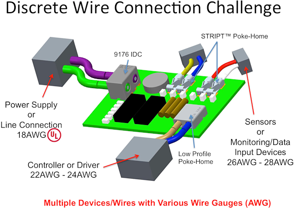
Figure 3.
IDCs Hold It Together
Insulation displacement connectors (IDCs) have been around for 50+ years. Although initially designed to provide quick and reliable terminations for computer cables, IDCs with particularly robust contact systems have migrated into the broader industrial and transportation markets over the past couple of decades.
The basic principle of an IDC contact is to eliminate the process required to prepare an insulated wire for termination. As such, IDC tines are designed to pierce the insulation, sandwiching the conductor between the two contact tines when a wire is pushed into the contact, to make the electrical connection.
Early IDC connectors were limited to specific wire gauges and office-level commercial applications, so they weren't especially robust. Now, though, several IDCs feature the materials and designs necessary to meet extreme temperature (+125°C) and automotive shock and vibration requirements.
IDCs based on phosphor bronze base material deliver the strength, performance, and yield characteristics necessary to provide a cold-welded and gas-tight wire connection capable of surviving harsh automotive and industrial environments, as well as the potting and over-molding processes required to waterproof or weatherize a device, by simply matching the conductor diameter to the size of the IDC slot.
Next page
The cross-sectional view of an IDC termination in figure 4 shows both the individual conductor stand deformation that creates a cold-welded, metal-on-metal bond and a STRIPT dual IDC contact especially designed to meet strict cost and performance objectives in small, but critical applications. Simple and reliable, these robust phosphor bronze IDC connectors and contacts can support solid, stranded, insulated, and un-insulated wires in sizes ranging from 28AWG up to 12AWG.
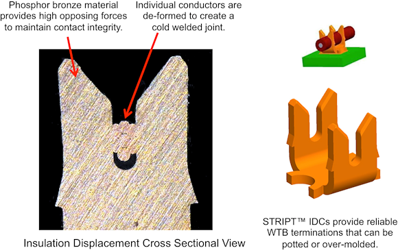
Figure 4.
WTBs And WTWs On Board
Compared to IDCs, poke-home wire-to-board (WTB) and wire-to-wire (WTW) connectors are relatively new. Introduced to the market within the last 10 to 15 years, they have continued to gain acceptance as a simple, yet reliable wire connection interface for securing several leaded devices with different wire gauges, lead diameters, board level positions, height constraints, and connection orientations to PCBs.
Poke-home connectors tend to be more field-friendly than other options, as their termination process only requires a standard wire stripper to prepare the end of the wire, which can then simply be poked into the connector or STRIPT contact to mate. The contact styles in this family range from single beam to dual beam, and, like all contacts, still rely on quality base materials, such as phosphor bronze or stainless steel, to effectively capture and hold a stripped wire in any one of several gauges and configurations and maintain the mechanical strength of that connection over time and temperature.
Typical examples of poke-home connectors, each with a unique contact geometry designed to meet specific AWG, height, or orientation requirements, are pictured in figure 5.
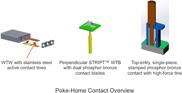
Figure 5.
Next page
Rounding It All Up
The compression, IDC, and poke-home contact technologies described above have all been around for many years now. They are typically available in a broad range of capabilities designed to satisfy the specific needs of various applications, many of which, including STRIPT contacts, are qualified for use in harsh environments and feature certifications including UL.
Due to the breadth of the product lines based on these technologies, selecting the one that will work best in your application might not always be obvious. So, connector suppliers can be crucial allies in identifying the best options for your particular needs. If you reach out to your supplier with detailed information about your application, they should be able to help reduce any unforeseen issues regarding product testing and launch.
For more details about connector and STRIPT contact products that incorporate these contact technologies, check out the virtual interactive interconnect sample kit pictured in figure 6.
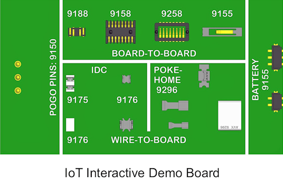
Figure 6.
About the Author
Tom Anderson has been in the connector industry for more than 30 years, and has held a variety of product marketing positions. For the last 10 years, he has been focused on developing new connector technologies for the automotive, industrial, and solid-state lighting markets.
[email protected]
http://www.avx.com