

Introduction
Positioning low-power radio frequency (RF) communications equipment requires that special attention must be taken to ensure proper line-of-sight (LOS) clearance between the transmitter and receiver. In regards to the TankScan monitoring system, this means a clear path between the monitor, which mounts on top of a tank, and the gateway which can be mounted near any power source. Failure to provide a clear LOS can manifest itself in two ways: missed reports and a shortened battery life. The guidelines set forth in this article will allow you to choose mounting locations that will optimize signal strength and battery life.
Background
Line-of-sight is defined as the straight line distance, clear of any objects, between the gateway antenna and each monitor it communicates with. Poor communications between a gateway and any monitor can cause two adverse effects: missed reports and a shortened battery life. If a monitor has trouble communicating with a gateway it may have to re-establish a connection while reporting a level. This process prolongs radio on time and further drains the battery. If a connection cannot be established, the tank level reading will be skipped.
TSM8000 monitors and their X2e, X2, and X4 gateways operate at 2.4-GHz frequency band and contain 18-dB (63-mw) radios. In addition, the X2 and X4 models have an additional 2 dB of gain from their antennas to provide 100 mW of output power. This allows for a 1,000-ft range with true LOS conditions. However, few installations have perfect LOS and some installation guidelines need to be observed. The following information will aid in antenna installation and positioning.
Many variables can affect the range of gateways and monitors, most prominent are obstructions blocking the signal path. The gateways are not intended for outdoor installation and must be placed indoors or inside an enclosure. This means that at least one obstruction (building wall, window, or enclosure wall) will exist between a gateway and any monitor unless an optional remote antenna is used, which reduces the 1,000-ft range. There is not an exact way to predict to what extent the range will be reduced, but there are a few general guidelines:
-
There may be up to 18-dB loss when sending radio signals through an exterior (non-metal) wall. The communication range may then be reduced to 125 ft. The type of wall (wood, concrete, masonry, brick, or combination) and the thickness of wall affect this number.
-
There may be up to 12-dB loss when communicating through a window. The communication range may then be reduced to 250 ft. The type of window, tinted, double-paned, thickness, and frame are all factors that contribute to range loss.
- Trees and foliage also attenuate 2.4-GHz signals, so gateway to monitor line-of-sights that pass through trees and foliage should be avoided.
It is not recommended to send radio signals through more than one window or non-metallic wall and never through a metal wall. A remote antenna should be used in these instances. This antenna can be used to improve the range and/or performance for other installations as well. Cable lengths of 10 ft. to 100 ft. (in 10-ft. increments) are available (see figure 1).
Fig.1: Cable length versus radio signal range recommendations. NR = Not Recommended
Antenna Mounting Guidelines
For best performance, the remote antenna should be installed at least 2.5-in. from metal surfaces such as walls and mounting poles. Ideally an antenna should have clear LOS communication to all monitors. The farther an antenna is from a monitor the more critical this becomes. Radio signals do go through, reflect off, and refract around obstructions, but they lose strength and range each time it occurs.
The mounting bracket for the remote antennas is a simple, lightweight design. It can be mounted to a 2-in. maximum diameter pole, or to a wall or other flat surface, and can be secured in a vertical or horizontal position. Optimal position is a vertical mounting.
TankScan remote antennas have a fat, concentric, donut-shaped propagation pattern (see figure 2) so height differences between gateway antenna and monitors are not critical and may be installed at different heights. Vertical angles of up-to 60 degrees between the gateway and monitor are acceptable.
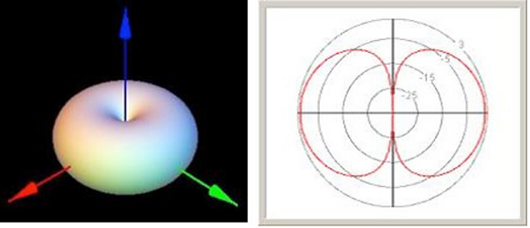
Fig.2: Remote antenna with a fat, concentric, donut-shaped propagation pattern.
The following examples show some of the various remote antenna mounting configurations. Every installation will be different, but it is important to maintain line-of-sight for each to provide the most robust communication.
Fig. 3: Pipe Mounted on Roof of Building
Fig.4: Mounted to Building Corner
Fig. 5: Mounted to Building Wall
Clear LOS
Often a gateway needs to talk to a cluster of tanks, sometimes positioned near obstructions such as other buildings, trees, or equipment. In these cases, a clear line-of-sight should be established to all monitors by picking an appropriate position for the gateway's antenna and/or raising the antenna up high enough to see all of the tank monitors.
Adequate antenna height above earth ground is important for successful radio communications. Radio signals propagate through the air in a zone shaped like a football, with the zone being very narrow at each antenna end and widest in the middle. As a very rough rule of thumb there should be 1 ft clearance radius (r) from all obstructions at the midpoint for every 100 ft. of transmit distance (see figure 6).
Fig.6: A rule of thumb indicates there should be a 1 ft. clearance radius (r) from all obstructions at the midpoint for every 100 ft. of transmit distance.
In figure 7 below, communication to Tank 3 is probably not possible from the North, while Tank 2 may or may not be blocked by Tank 1 from the West. A good rule of thumb to follow is that if each monitor is within range and an observer can clearly see the gateway antenna from the monitor's position, they should be able to communicate.
Fig. 7: If the monitors are within range of each other and an observer can clearly see the gateway antenna from a monitor's position, they should be able to communicate.
Indoor Installations
Many sites have tanks located within the same building as their gateway. Guidelines for signal strength and range loss within a building include:
- 2-dB to 9-dB loss when shooting through a sheet rock interior wall
- 2-dB to 6-dB loss when shooting through an office panel
- 2-dB to 6-dB loss when shooting through a rack of equipment
***As a rule of thumb, every 6 dB of loss decreases signal range by 50%.
Indoor installations present unique conditions as there is less open space for a LOS clearance zone and the potential for much more interference. Line-of-sight communication is rarely possible. Because of the nature of indoor environments, it is recommended to limit the communication range to 250 ft.
Summary
For reliable monitor-to-gateway communication there are two basic rules:
- Do not exceed radio signal range of gateways and monitors.
- Establish clear Line-of-sight communication between gateways and monitors using a remote antenna, if necessary.
Following the guidelines set forth in this article will insure proper line-of-sight clearance, resulting in reliable RF communication and maintain the expected battery life.
About the Author
Prior to earning his Bachelor of Science degree in electrical engineering, John Brewer served for 5 years in the United State Air Force as an Electronics Technician in a mobile communication squadron. This prepared him well for his university studies and career afterwards. As part of his 18-year career in design and product development, he counts more than 10-years experience in installation and operation of wired and wireless communication systems.
Related Stories
Laird M2M Antenna Offers More Bandwidth From A Low-Profile Design
Echo Therapeutics, Inc. Achieves Wireless Mobile Communication Milestone
Pasternack Expands Lines of Microwave and Millimeter Wave Right Angle RF Adapters
Galtronics unveils New EXTENT Omni Whip Product Line Developed for Small Cells and Outdoor DAS