
German automotive system supplier Robert Bosch created the Controller Area Network (CAN) to enable robust serial communications while decreasing wiring harness weight and complexity. The current version of the protocol, 2.0B, provides transmission speeds up to 1 Mbps.
Since its inception, CAN has moved from automotive applications to industrial control. Now technicians and engineers are starting to use it in medical and test equipment. The test, measurement, and control community is discovering just what this bus can do when it is coupled with smart sensing technology.
How Is CAN Used?
The CAN protocol creates a communications path that links all the nodes connected to the bus and enables them to talk to one another. Depending on how the designer has configured the system, there may or may not be a central, or main, node. The protocol defines aspects of how each node can respond, but it leaves tremendous flexibility to the system designer to implement the nodes in ways that suit the particular application.
Figure 1 shows an automotive application in which several nodes in a vehicle door are connected through a door node controller to the main CAN bus. As mentioned before, the network need not have a controller node; each node can just as easily be connected to the main bus. Applying the concept shown in Figure 1 to a sensor network is as easy as changing the type and description of the nodes (see Figure 2).
What Makes Up a Node?
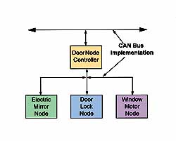
Figure 1. In this automotive application, the CAN bus is used to interconnect the individual nodes that detect button presses and control motors or solenoids in a door. Each node can communicate with any other node.
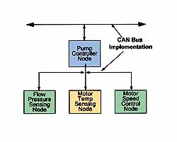
Figure 2. CAN is a robust protocol, which makes it well suited to interconnect sensor and motor control nodes in industrial environments.
The term node describes a portion of the overall system or network. Each node can have one function, or it can have many functions. Depending on the system configuration, different nodes may transmit messages at different times based on the function(s) of each node. For example:
A node may transmit a message only when a system failure occurs.
A node may transmit messages continually, such as when it is monitoring the flow rate from a pump in a control loop.
A node may take action or transmit a message only when instructed by another node, such as when a fan controller is in structed to turn a fan on when the temperature-monitoring node has detected an elevated temperature.
Figure 3 outlines the components of a generic node. In this node, a signal from a sensor passes through signal conditioning circuitry and then into the A/D converter. The node feeds the data from the converter into the microcontroller for analysis. Based on the function of the node, the microcontroller may immediately pass the information on to the bus for other nodes to use, or it may wait for a value higher than a set point before transmitting any data. The bus transceiver converts the standard logic signals from the microcontroller to the signal levels used on the physical CAN bus.
CAN Messages
The CAN protocol uses a message-based data format in which information is transferred from one location to another by sending a group of bytes at one time. Unlike address-based systems, every node in this system listens to every message on the bus (and will acknowledge if the message was properly received) to determine if it needs to take action.
Every message has an identifier field consisting of either 11 or 29 bits. The message can also contain data, but its not required. The node uses the identifier to determine if the incoming message should be accepted and acted on or discarded.
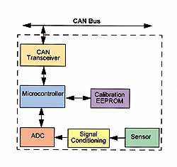
Figure 3. A typical smart sensor node is made up of both digital and analog components, which allow the sensor data to be captured, transformed, analyzed, and transmitted to other nodes in the system. System designers often create generic node hardware, which can be easily configured for different node applications.
When one node wants to send data to any other node(s), it assembles a message with the proper identifier and data, checks to see if the bus is free, and then transmits the message. Every other node captures the message and examines it to see if it is required to take some action. A single node may act on the message, or many nodes may accept the message and act on it. For example, a temperature-monitoring node may send out temperature data that are acted on only by a node that displays the current temperature. But if the temperature sensor detects an overtemperature situation, then many nodes might act on the information.
With the message-based format, you can add nodes to the bus without reprogramming the other nodes to recognize the addition. The new node will start receiving messages from the network immediately.
Another useful feature built into the CAN protocol is the ability of a node to request information from other nodes. This is called a remote transmit request, or RTR. This is different from the previous example because instead of waiting for information to be sent to it, the node specifically requests that the data be transmitted.
CAN Protocol Layers
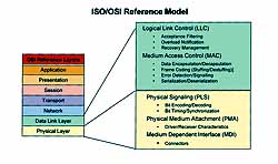
Figure 4. The ISO/OSI reference model defines seven layers of system implementation for network applications, which allows standardization of network components from different manufacturers, making them interchangeable. The CAN protocol defines the lower two layers of the model with the exception of the medium-dependent interface (MDI) in the physical layer. The upper layers were left undefined by CAN so that users could create interfaces that met their specific requirements. Some upper-level protocols, such as DeviceNet (Allen-Bradley) and SDS (Honeywell), are based on the CAN protocol.
Most network applications follow a layered approach to system implementation. This enables interoperability among products from different manufacturers. The Inter national Standards Organization (ISO) created the Open Systems Interconnection (OSI) Network Layering Reference Model to serve as a template for this approach (see Figure 4).
The CAN protocol implements most of the features of the lower two layers of the reference model. But Bosch did not include the communications medium portion of the model in the CAN specification because he wanted to give system designers the freedom to adapt and optimize the protocol on multiple media (e.g., twisted pair, single wire, optically isolated, RF, and IR) for maximum flexibility. A common method of implementing the physical layer is by specifying a 5 V differential electrical bus as the physical interface (see Figure 5). Such an implementation is fully defined in ISO-11898.
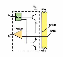
Figure 5. Many CAN systems use a transceiver to implement the physical layer of the protocol. A typical transceiver operates from a 5 V supply and delivers a differential signal of 03 V for the actual data transmission. The transceiver also provides protection against transient voltages on the data.
The rest of the layers of the OSI protocol stack are left to be implemented by the system software developer. Higher Layer Protocols (HLPs) are generally used to implement the upper five layers of the OSI reference model. Two of the most notable industrial control HLPs are Allen-Bradleys DeviceNet and Honeywells Smart Distrib uted System (SDS).
Higher Layer Protocols are used to:
standardize startup procedures, including the bit rates used
distribute addresses among participating nodes or types of messages
determine the structure of the messages
provide system-level error handling
This is by no means a full list of the functions that HLPs perform, but it does describe some of their basic func tionality.
Most CAN systems implement the physical layer of the protocol by using some kind of transceiver (see Figure 5). This device connects the CAN High (CANH) and CAN Low (CANL) pins to the CAN bus with a differential signal of 03 V. A trans ceiver also provides transient protection of ±200 V and fault protection by acting as a barrier that can withstand voltages of ±40 V.
Figure 6. The standard data frame is one of several frame types used in the CAN protocol. The data frame is made up of several fields, which include 11 bits for the identifier, up to 8 data bytes, and 16 bits of cyclical redundancy check sum error checking. The nodes use the identifier field to determine if a message should be acted on. It is also used in the bus arbitration scheme to prevent bus collisions if more than one node begins transmitting at the same time.
CAN Message Frames
The CAN protocol defines four types of messages, or frames. The first and most common is a data frame, which is used when a node transmits information to any or all other nodes in the system. The second most common, a remote frame, is used when one node requests data from another node. The other two frame types are used to handle errors. A node generates an error frame when it detects one of the many protocol errors defined by CAN. And the protocol calls for an overload frame when it requires more time to process messages already received.
Standard and Extended Data Frames. Data frames consist of fields that provide additional information about the message. Embedded in the data frames are arbitration fields, control fields, data fields, cyclic redundancy check sum (CRC) fields, a 2 bit acknowledge field, and an end of frame.
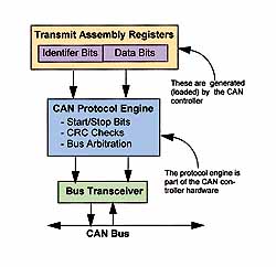
Figure 7. To transmit a message, the node first must load the message identifier, data bytes, and control bits into the transmit message assembly registers. The node then transfers the data to the CAN protocol engine. The protocol engine creates the actual frame by inserting the frame elements, such start and stop bits and interframe space bits. The protocol engine also handles bus arbitration, cyclical redundancy check sum calculations, and looks for transmission errors.
The arbitration field prioritizes messages on the bus. Because the CAN protocol defines a logical 0 as the dominant state, the lower the number in the arbitration field, the higher the priority of the message on the bus. For a standard data frame, the arbitration field consists of 12 bits11 identifier bits and 1 RTR bit(see Figure 6). Extended data frames are identical to the standard data frames except that the arbitration field is 32 bits (29 identifier bits, 1 bit to define the message as an extended data frame, 1 unused bit, and an RTR bit).
Remote Frames. As described in the preceding section, the RTR is used when a node requests information from another node. This might be used when a sensor is monitoring the temperature but transmits a signal only when an overtemperature condition exists or when another node requests the sensor to transmit the current temperature. A remote frame is sent as a command and has no data field.
Error Frames. When a node detects one of the errors defined by the CAN protocol, an error frame is auto matically sent by the controller.
Overload Frames. These frames tell the network that a node is busy and is not ready to receive additional messages at the time.
Bus Arbitration. CAN is based on the carrier sense multiple access (CSMA/CD) protocol. Carrier sense means that before any node sends a message, it must monitor the bus for a period of inactivity before trying to send a message. Multiple access indicates that once the period of inactivity occurs, every node on the bus has an equal opportunity to transmit a message. The CD stands for collision detection. If two nodes on the network start transmitting at the same time, the nodes will detect the collision, and one of the nodes will stop transmitting.
CAN uses a nondestructive bitwise arbitration, which means that messages remain intact after arbitration is completed even if collisions are detected. All the arbitration takes place without corruption or delay of the message that wins the arbitration.
There are a couple of things required to support nondestructive bitwise arbitration. First, logic states must be defined as dominant or recessive. Second, the transmitting node must determine if the logic state it is trying to send actually appears on the bus. CAN defines a logic bit 0 as a dominant bit and a logic bit 1 as a recessive bit. A dominant bit state will always win arbitration over a recessive bit state.
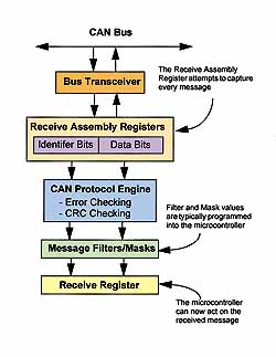
Figure 8. Every active node reads every message transmitted on the bus. When a node receives a message and determines that there are no errors with the message, the identifier field of the message is checked against filter and mask registers to determine if the message should be acted on. Different CAN controllers implement filters and masks in different ways, and most controllers have multiple receive registers to increase the throughput of message reception. The system designer is free to determine how to use the receive buffers and filters to manage messages in a way that suits their needs.
For example, suppose two nodes are trying to transmit a message at the same time. Each node will monitor the bus to make sure the bit that it is trying to send actually appears on the bus. The lower priority message will at some point try to send a recessive bit (a logic high), and the monitored state on the bus will be a dominant bit (a logic low). At that point, the node sending the lower priority message loses arbitration and immediately stops transmitting. The higher priority message will continue until completion, and the node that lost arbitration will wait for the next period of inactivity on the bus and try to transmit its message again.
Creating and Sending a Message
Every CAN controller handles the details of message transmission and reception differently, but the overall concept is the same for most devices. A message is typically created in the controller by filling registers with the proper information. This includes the identifier information that determines which nodes receive the message and the data bytes that are required (see Figure 7). Many CAN controllers have multiple transmit buffers so that messages can be preloaded in preparation for a particular event.
After the data have been loaded, the controller can be given the command to transmit the message. When the controller re ceives the command, it checks to see if the bus is busy before beginning the transmission. As transmission of the message is occurring, the controller checks for bus collisions and other transmission errors. Other than loading the buffers and giving the command to transmit, all the details of this proc ess are handled in hardware by the CAN protocol engine. The controller automatically checks for the bus-free state and performs bit arbitration and error checking. Most CAN controllers maintain a series of status bits that can be used to determine if a transmission is complete and if any errors occurred during the transmission.
Receiving and Processing a Message
As mentioned previously, the CAN protocol is a messaged-based system that requires every node to listen to every message on the bus. Each node must determine if it should discard the message or take some action. A node determines if it should accept a message by examining the identifier bits. Inside the controller, filters and masks are compared against the identifier bits to see if there is a match. If the identifier bits match one or more of the filters, then some action will be taken by the node.
The system designer determines how the filters and masks are used. Most CAN controllers have multiple receive buffers, which increase the ability of the controller to handle higher transmission rates and reduce the chance of an overload condition, where the controller is still busy processing one message when another message is being transmitted. Most CAN controllers have sophisticated methods of using masks, filters, and interrupts to minimize message processing requirements (see Figure 8).
Error Handling
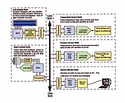
Figure 9. A typical smart sensor network is made up of nodes that have different functions. Some nodes will only transmit data, some will receive data, and some may have multiple functions. The CAN bus provides a robust means of interconnecting nodes and allows each node to communicate with any other node. If the system has many nodes and there is a lot of traffic on the bus, message identifiers can be organized to include a scheme that ensures that priority messages are processed first.
Because CAN was initially designed for use in automo biles, the protocol had to efficiently handle errors if it was to gain market acceptance. With the release of version 2.0B of the CAN specification, the maximum communication rate was increased eight times over that of version 1.0 to 1 Mbps. At this rate, even the most time-critical parameters can be transmitted serially without latency concerns. In addition, the CAN protocol has a comprehensive list of errors that it can detect, which ensures the integrity of messages.
CAN nodes can determine fault conditions and transition to different modes based on the severity of the problems encountered. They can also differentiate between short disturbances and permanent failures and modify their functionality accordingly. CAN nodes can transition from functioning as a normal node (i.e., being able to transmit and receive messages normally) to shutting down completely (bus off) based on the severity of the errors detected. This feature is called fault confinement.
A faulty node cannot monopolize the bandwidth of the network because the fault is confined to that one node, which shuts off before bringing the network down. This feature guarantees bandwidth for critical system information.
Errors Detected. The CAN protocol defines five errors.
CRC Error. The transmitting node calculates a CRC value and then transmits the value in the CRC field. All nodes on the network receive the message, calculate a CRC, and verify that the CRC values match. If the values do not match, a CRC error occurs, and the node generates an error frame.
Acknowledge Error. In the acknowledge field of a message, the transmitting node checks if the acknowledge slot (which it has sent as a recessive bit) contains a dominant bit. Such a bit acknowledges that at least one node correctly received the message. If the bit is recessive, then no node received the message properly. If an ac knowledge error occurs, the node generates an error frame.
Form Error. If a node detects a dominant bit in the end of frame, interframe space, acknowledge delimiter, or CRC delimiter, the protocol defines this to be a form violation, and a form error is generated.
Bit Error. A bit error occurs if a transmitter sends a dominant bit and detects a recessive bit or if it sends a recessive bit and detects a dominant bit. If a bit error is detected, the node generates an error frame and resends the original message after a proper intermission time.
Stuff Error. The CAN protocol uses a non-return-to-zero (NRZ) transmission method. This means that the bit level is placed on the bus for the entire bit time. CAN is also asynchronous, and it uses bit stuffing to allow receiving nodes to synchronize by recovering clock information from the data stream. Receiving nodes synchronize on recessive-to-dominant transitions. If there are more than five bits of the same polarity in a row, CAN automatically stuffs an opposite polarity bit in the data stream. The receiving node(s) use it for synchronization but ignore the stuff bit for data purposes. If between the start of frame and the CRC delimiter, six consecutive bits with the same polarity are detected, then the bit-stuffing rule has been violated. A stuff error then occurs, the node sends an error frame, and the message is repeated.
Error States. Error frames or error flags notify all nodes that an error has been detected. The transmission of an erroneous message is aborted, and the frame is repeated as soon as the message can again win arbitration on the network. Each node is in one of three error states: error active, error passive, or bus off.
Error Active. This is the normal operational mode, allowing the node to transmit and receive messages without restriction. A node is error active when both the transmit error counter (TEC) and the receive error counter (REC) are below 128.
Error Passive. A node becomes error passive when either the TEC or the REC ex ceeds 127.
Bus Off. A node goes into the bus-off state when the TEC is >255 (receive errors can not cause a node to go bus off). In this mode, the node cannot send or receive messages, acknowledge messages, or transmit error frames of any kind. The protocol achieves fault confinement in this way. CAN defines a bus recovery sequence that allows a node in the bus-off mode to recover, return to error active, and begin transmitting again if the fault condition is removed.
Implementing CAN for a Smart Sensor Application
Applying the CAN protocol to a smart sensor network is a natural progression from existing sensor networks. Industrial sensor networks have many of the same requirements that automotive applications require; most important are fast and robust communication.
The network shown in Figure 9 is an example of how a small network can be designed. In this example, there are five nodes:
An LCD node captures messages from the temperature sensor node and the pressure sensor node and displays the data from one or the other.
A temperature sensor node takes a temperature reading every 500 ms and sends the results out on the bus. The data from the node can be used to compensate the pressure sensor on the pressure sensor node and can also be used to adjust the contrast for the LCD.
A pressure sensor node takes a pressure measurement every 500 ms and sends the results out on the bus.
A system monitor node captures all messages and relays them to a PC. You can then use the PC to monitor system activity and notify an operator if a problem occurs.
A motor control node accepts messages from the temperature sensor node and uses the information to adjust the fan motor speed. It also monitors the current drawn by the motor and transmits the data out on the bus.
This example shows the concept of a distributed system architecture being applied to a control system. The smart sensor nodes that take temperature and pressure data are simply putting the data on the bus and letting other nodes in the system process the data and determine if action needs to be taken.
Advantages of Using CAN
Standardization of System Components. Many components used by the nodes become standardized. Because each node is connected to the same bus and communicates at the same baud rate, all hardware and microcontroller firmware is consistent from node to node. Each node will most likely maintain different transmit buffer information and different filters that determine which messages to receive, but all hardware and message-control base code are the same for all nodes.
Robust Protocol. The CAN protocol was designed for automotive applications and was developed to work in systems in which circuit noise, short circuits, and voltage variations are commonplace. The sophisticated error checking and handling integrated in the protocol allow these problems to occur without damaging the system or bringing the network down.
Changing Nodes Without Shutting Down the Network. Because CAN is a robust protocol, you can add or remove nodes from the network without bringing the overall system down. If you have to upgrade the system, you can add new nodes without affecting existing nodes.
Simplified Wiring of Nodes. Using a network connection for sensor nodes reduces or eliminates point-to-point wiring and makes it easier to modify existing systems. By using the CAN bus, wiring harnesses and connectors become common between nodes.
Large Base of Products and Development. Today, more than a dozen semiconductor companies provide CAN controllers. These come in a variety of forms, either as stand-alone units or as components integrated in microcontrollers. In addition, as many as 20 companies worldwide provide CAN development tools. And organized industry groups sponsor and run conferences and trade shows focused on CAN, allowing system designers to find out what resources are available to them and learn what is new in the industry.
Conclusion
The CAN protocol was optimized for systems that need to transmit and receive relatively small amounts of information (as compared with Ethernet or USB, which are de signed to move larger blocks of data) reliably to any or all other nodes on the network. While not every sensor system fits this criterion, it does cover many embedded sensor systems.
Because the protocol is message based, any node can send a message to any other node. This gives tre mendous flexibility to the system designer when items such as system cost, performance, and upgradability are being measured against one another.
The CAN protocol is robust and uses sophisticated error checking and handling, which allows errors and failures to occur without shutting the entire system down. The error containment also allows sensor nodes to be added to or removed from the system while the network is in operation. These error handling features effectively guarantee that bandwidth will always be available for the transmission of critical messages. With all these benefits built into the protocol, it makes an excellent choice for smart sensorbased systems.
For Further Information
CAN In Automation (CIA) Industry Group, www.can-cia.de (industry information and related links).
Open DeviceNet Vendor Association (ODVA), www.odva.org (DeviceNet Support). Pazul, Keith. Controller Area Network (CAN) Basics, Application Note AN713, Microchip Technology Inc.
Hitachi Infineon Technologies Corp. Microchip Technology Inc. Mitsubishi Motorola National Semiconductor Corp. NEC OKI Philips ST Microelectronics Temic (now owned by Atmel Texas Instruments Toshiba Unitrode Diversified Engineering & Manufacturing.Inc. EMS Dr. Thomas Wuensche Embedded Micro Software Hilscher IXXAT Automation GmbH Kvaser AB National Instruments Softing GmbH Vector CANtech, Inc.
Zanthic TechnologiesCAN Silicon Manufacturers
CAN Tool Suppliers
Fujitsu
www.fujitsu-fme.com
http://semiconductor.hitachi.com
www.infineon.com/us/micro/can/prods.html
www.microchip.com
www.mitsubishi.com
www.motorola.com
www.nsc.com
www.nec-global.com
www.oki.oki-europe.de/auto
www-us.semiconductors.com/can
www.st.com
www.temic.com
www.ti.com/sc/docs/products/dsp/overview.htm
www.toshiba-europe.com
www.unitrode.comDearborn Group, Inc.
[email protected]
www.diversifiedengineering.net
www.ems-wuensche.com
www.emicros.com
www.hilscher.com
www.ixxat.de
www.kvaser.se/can/main.htm
www.ni.com
www.softing.com
www.vector-cantech.com
www.zanthic.com