
In 1834 Jean Peltier discovered that running an electric current across a junction of two dissimilar metals caused heat to transfer across the junction, cooling one side while heating the other. Because of the low efficiency of this effect in metals, and their high thermal conductivity, which causes heat to rapidly leak back across the junction, this Peltier effect was little more than a laboratory curiosity.
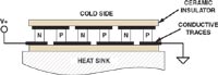 Figure 1. TEC modules consist of alternating slugs of N- and P-type semiconductor material wired in series |
Out of the Lab
Fast-forward 170 years. The availability of semiconductors such as bismuth-telluride, which have low thermal conductivities and very pronounced Peltier effects, now makes it possible to realize practical solid-state refrigeration devices. A modern thermoelectric cooler (TEC) module consists of alternating slugs of N- and P-type semiconductor material wired in series (Figure 1). When a positive DC voltage is applied to this assembly, heat is pumped from the top surface and down to cool the heat sink. If the voltage is reversed, the top surface is heated. The bidirectional nature of a TEC allows its use for stabilizing thermal loads at temperatures both lower and higher than ambient. Figure 2 shows a typical finished device.
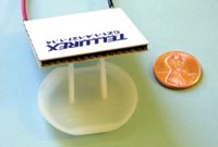 Figure 2. Here's a typical finished TEC |
Quirks and Requirements
Although TEC modules provide a near-magical refrigeration/heating unit with no moving parts, TECs, as do all real-world components, have their quirks and requirements for care and feeding. Not paying attention to these needs may cause the magic to leave the device—sometimes in the form of smoke.
First, when you pump heat, it has to go somewhere—one of those pesky laws of thermodynamics. So you absolutely must provide an adequate heat sink on the hot side of the TEC or it tends not to work very well or last very long. The solder used to bond the semiconductor pellets that form a TEC has a low melting temperature and can be easily damaged through overheating.
A second characteristic of TECs also results from fundamental thermodynamic limitations. A TEC can pump only so much heat "uphill" against a temperature gradient. In other words, the bigger the difference in temperature between the hot and the cold sides, the less heat gets pumped. One reason is simply that heat leaks back from the hot side to the cold side. TECs therefore have a maximum temperature differential they can sustain, usually about 60°C–70°C; at this point they are pumping heat from the cold to the hot side as fast as it is leaking back, and this limits how much you can cool the cold side. In practice, you can expect to sustain temperature differentials on the order of 40°C with most commercially available TECs.
For example, if you maintain the heat sink at room temperature (20°C), you might be able to get the cold side down to –20°C with proper insulation.
Maximum temperature differential can be sustained only when the device is running at or near maximum ratings, and this brings up another point. Like all other two-terminal semiconductor devices, TECs have voltage and current ratings. Exceeding these ratings will not only severely shorten the device's useful life, but also can be counterproductive—a TEC can actually be less effective at removing heat when running over maximum ratings than when running at maximum. So you need to carefully note both maximum device ratings and the manufacturer's recommended operating conditions.
A "Gotcha"
All the above is basic physics. The big, but not obvious gotcha with TECs is the matter of controlling them. All those solder connections don't especially like being temperature-cycled on a regular basis, and doing so tends to reduce their reliability. For this reason, a simple ON/OFF thermostatic control like the one I wrote about in March 2006 (http://tinyurl.com/mhfaq) will probably not be suitable for most TECs because of the continuous temperature cycling. A controller that maintains the TEC in a steady-state condition is a better choice.
The TEC drive voltage, however, does not need to be DC—a suitably fast (kilohertz range) pulse-width modulated (PWM) signal will also work as long as the PWM frequency is faster than the TEC's thermal time constants. But there is one caveat with using PWM drive: the maximum instantaneous current and voltage should never exceed the TEC's maximum ratings.
Applications
TECs have numerous applications beyond the ever-popular portable beer cooler. Fingernail-sized models provide precision temperature control for semiconductor telecommunications lasers. Because the optical communications channels in schemes such as dense-wave division multiplexing (DWDM) might be separated by only a few nanometers, wavelength control on the order of picometers is necessary to keep channels from interfering with each other. Stabilizing a laser's output frequency requires that its temperature be maintained to within a few tenths or even hundredths of a degree C.
Another application is in IR imaging systems. To obtain maximum sensitivity, the sensors must be cooled way below freezing. As noted above, it can be difficult to cool things much more than 40°C below ambient. To achieve lower temperatures, you can stack multiple units on top of one another so that each sees only part of the total gradient. In multistage cooling schemes TECs are typically configured like a step pyramid, with the largest one pumping heat into the ambient heat sink and the smallest one located at the cold surface.
Because of their unique ability to provide "cold-on-demand," their lack of moving parts, and their small size, thermoelectric modules are among the "coolest" solid-state components out there.
TEC Sources
Marlow Industries www.marlow.com
Melcor www.melcor.com
Tellurex Corp. www.tellurex.com