
A few weeks ago I received an ad in the mail for a high-end current meter that promised resolution down to 10 atto-amperes, 10–17 A. This is a really impressive spec—especially when you consider that it corresponds to detecting the passage of only 60 electrons per second (there goes one now!). Resolutions like this make me think about how huge the currents (picoamps–amperes) are that I normally have had to worry about in my designs. The dynamic range of 10 aA to 1 A is pretty mind-boggling; 10 aA is to 1 A roughly as 1 ft. is to the distance to the star Proxima Centauri (~4.24 light years away).
 Ed Ramsden |
Despite being a really small current (or a really large one, depending on your viewpoint), nanoamps and picoamps become very significant when designing precision transducer interfaces. In this context, a stray nanoamp here and another one there, and pretty soon you are talking about real current. And real measurement errors.
Let's consider using an instrumentation amplifier (in amp) as the front end for a thermopile-based IR sensor. The in amp is a TI INA126, which provides single-resistor programmable gains from 5 to a few thousand, 100 μV (typ.) of input offset voltage, and 10 nA (typ.) of input bias current. For purposes of simplicity, I am going to ignore the effects of input bias offset current. The IR sensor is a Melexis MLX90247 thermopile, which provides a signal of 40 μV/°C and has a 60 kΩ source impedance. Given this sensitivity and input voltage offset, you could expect perhaps 2°C–3°C additional system error from using this amplifier. Figure 1 shows a first cut at an interface circuit to provide a gain of 1000.
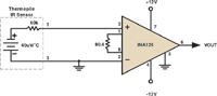 Figure 1. |
But wire up this circuit, and the first thing you might notice is an ~500 mV output signal—with no input causing it. While you might expect 100 mV of output error from the input offset voltage (100 μV X 1000), an order of more error is present. Where is it coming from? The answer lies in the in amp's 10 nA input bias current. This current into the negative input on the negative lead is being drawn from ground, so it doesn't affect the voltage. The 10 nA at the positive input, however, is being drawn through the 60 kΩ impedance of the sensor, resulting in 600 μV of additional voltage at that point. This error gets accurately amplified, along with the voltage offset and whatever signal is hiding in there. So the problem has two root causes: The small, but finite bias current demanded by the in amp, and an unbalanced sensor source impedance. The in amp's two inputs see radically different source impedances (60 kΩ vs. 0 Ω), and that's what creates the error.
There are several potential solutions. You can buy an in amp with lower input bias current and offset voltage specs. A FET input in amp will have an input bias current in picoamps but might also have a higher offset voltage. A better in amp may also cost more, which can be a bad thing if you are buying a lot of them.
Indiscriminately shoving better parts into a circuit is generally a very unsatisfactory way to improve performance. Precision analog design is part science and part art, and getting the most mileage out of every component is part of the art. Although the electron-counting super-ammeter that inspired this column must incorporate some truly first-rate components, someone must have done some serious engineering (and maybe some magic) to support the claimed performance.
A second, and more artistic way to fix the input bias current problem, while still using the INA126, is to artificially balance the sensor source impedances (Figure 2). In this circuit, the in amp inputs see a differential impedance of a little less than 60 kV, and identical common-mode impedance (1 MV), so the 10 nA of bias current from each input causes both inputs to shift by 10 mV. While much larger than the previous error, both inputs are affected identically and no overall error results. You may ask about the case where the 1 MV resistors don't match exactly. Decent matching is certainly needed, but small mismatches (1%) result in errors of only a few microvolts at the input. (I will leave this for you to demonstrate.)
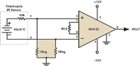 Figure 2. |
One remaining difficulty is the high common-mode impedance, which can make the inputs susceptible to noise. For the final brush stroke you could add bypass capacitors that reduce the impedance at high frequency but which don't significantly affect the DC and low-frequency impedance. This is a temperature sensor after all, so nobody expects it to be really fast.
Ed Ramsden, BSEE, a member of the Sensors Editorial Advisory Board, designs sensors for the heavy-truck industry in Portland, OR.