

 |
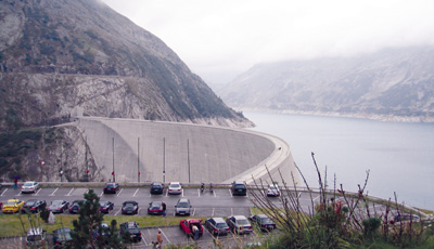
Xiaowan hydropower station on the Lanchang River in Yunnan province, China, consists of a double-curvature arch dam, 292 meters high. Construction began in January 2002 and is expected to conclude by the end of 2010. Steep slopes in the river valley, both natural and engineered, pose critical problems for construction engineers. Heavy rain or further rock excavation could cause slopes near the arch dam to slide. To reduce landslide risk, engineers have employed several conventional techniques, traditional surveying equipment, and specialized geotechnical instrument to monitor the stability of the high-risk slopes. They also used GPS as a monitoring tool for high-risk slopes.
Usually, several observation points must be monitored to fully understand the stability and any ongoing deformation that could cause slope failure. For example, it required 16 observation points to adequately monitor a high-risk slope measuring 300 by 500 meters, or 0.15 square kilometers.
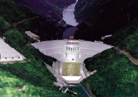 Architectural model of the completed Xiaowon dam and hydropower station |
GPS offers greater accuracy and is highly automated and less labor intensive than the conventional techniques used during the stability monitoring of the high-risk slopes. However, GPS does have disadvantages, the major drawback being the high cost associated with placing a permanent GPS receiver at each monitoring point. Xiaowan power station has many steep slopes; therefore, conventional GPS monitoring methods have significant limitations here.
We have implemented a new approach linking a single GPS receiver with multiple antennas mounted at several monitoring points. We developed a dedicated electronic switching device — the GPS multiple-antenna switch (GMAS) — to connect the receiver with the antennas, significantly reducing the required hardware investment.
Other technologies include a new electronic switching device for GMAS, General Packet Radio Service (GPRS) wireless data communication, and a microamplifier.
System Description
Figure 1 outlines the GPS multiple-antenna system for slope-deformation monitoring. The system includes three main parts: the GPS GMAS with antenna array and low-noise amplifier, control center, and the GPRS wireless data communication system. The GMAS is the core of the slope-deformation monitoring system.
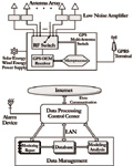 Figure 1 The outline of a GPS multiple-antenna deformation monitoring system |
Switching Device. Adjacent photos show the GMAS, an electronic switching device designed for a multiple-antenna GPS deformation-monitoring system. Patented in 2002 in China, the GMAS connects eight antennas to a single GPS receiver. By switching antenna array in turn, the receiver monitors eight separate points. GMAS with different interfaces and connectors support two modes of commercial GPS receivers. One type can connect directly with any standard survey-type GPS receivers and antennas. In the other mode, GPS cards are embedded into the GMAS.
The GMAS sequentially allocates time to each antenna. The main parameter entered into the GMAS is the time allocated to an antenna in each round of measurements. The receiver makes standard pseudorange and carrier-phase observations for each antenna.
Two options are available when allocating time to each antenna. The receiver can be connected to an antenna for one epoch of GPS measurements only (say, for 10 seconds) and then connected to the next antenna in rotation. A time series from each antenna is then built up, with additional data added each time the antenna is revisited. This option causes cycle slips in the data series as the GMAS switches from one antenna to the next. The well-known methods of cycle-slip detection and reconstruction do not work in this case. However, when the rate of deformation of the monitored feature is low, the integer ambiguities for each epoch may be determined based on the prior known coordinates of the monitored points.
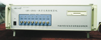 Front of the multiple-antenna switching device |
Alternatively, the receiver could remain connected to each antenna for a set period of time to allow it to acquire a number of epochs of data from an antenna before it switches to the next. For this second option, the data from each antenna can be processed as a short-time series using standard double-differencing techniques with initial-ambiguity resolution.
In deformation monitoring, depending on the type and nature of the monitored features, sometimes the timing — that is, the rate of acquiring and processing the data — is important to obtain a warning of antenna motion as soon as possible. In other cases, the accuracy of measurements is more important. Therefore, users must choose an appropriate option for a given situation.
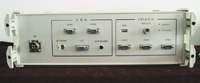 Back of the multiple-antenna switching device |
For the Xiaowan hydropower station, therefore, we chose the second option for high-accuracy measurements.
Microamplifier. The antennas were connected to the GMAS by coaxial cables, but there is a practical limit to how long these can be. Even with low-loss cables, signal attenuation reduces the signal-to-noise level below a usable threshold for cables much longer than approximately 30 meters. Low-noise preamplifiers help overcome the signal-to-noise losses for longer cable runs; alternately, a system of fiber-optic cables can be used.
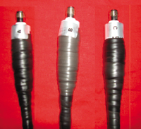 Low-noise microamplifier |
As a general requirement, the length of a coaxial cable between a GPS antenna and the GMAS must be less than 30 meters. This would severely limit the slope-monitoring area at Xiaowan. From an engineering viewpoint, we developed low-noise microamplifiers for GMAS.
The maximum distance between antenna and GMAS is now as great as 1 kilometer. These microamplifiers have been used successfully for steep-slope monitoring of the Xiaowan hydropower station.
Data Link. Currently a fixed telephone line, a dedicated data line, a wireless global system for mobile communications (GSM) data line, and radio transmitters can be used as data communication links between the control center and the slope zone. The steep slope in this study is in dangerous area. Because of the dangerous terrain and the cost of data communication, we chose GPRS communication technology, as being less expensive and more convenient than other communication methods.
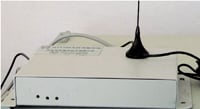 GPRS transmitter device |
GPRS is a standard for wireless communications which runs at speeds as fast as 115 kilobits per second, and it is particularly well suited for sending and receiving large volumes of GPS raw data. Using GPRS devices developed by the authors and the user-defined communication protocol, we have sent large volumes of GPS raw data automatically from steep slope at the Xiaowan hydropower station to the control center.
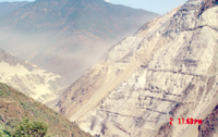 Number two slope seen from dam |
Implementation
The physical conditions of the Xiaowan hydropower station are complicated both seismically and geologically in its outer surroundings; however, the dam site itself is in a relatively safe zone with considerable stability. The arch dam is designed to rest on a V-shaped deep valley formed by massive mountains on both banks, more than 1000 meters above the river surface. The construction involves slope-cutting. The stability of steep slopes in the vicinity of the dam is interrelated to the whole construction project. The photograph above shows where the shoulder of the arch dam is located at the Number Two steep slope. The slope is 700 meters high, and the mean slope gradient is approximately 40–45 degrees. Thus, we needed to place a strong emphasis on monitoring steep slope Number Two.
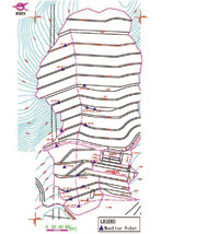 Figure 2 GPS network of Number Two steep slope |
We set up the GPS network to perform the monitoring work. It included 16 monitoring stations and two base stations. Figure 2, a depiction of Number Two steep slope produced by Autocad software, shows the distribution of the GPS network, with an alternative version of the same network shown in Figure 3. Two base stations, B1 and B2, stand some distance from the monitoring zone, and 16 monitoring stations are distributed across Number Two steep slope. Photographs at the right and on the cover of the magazine show the GPS antennas at the base station and monitoring station, respectively.
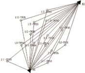 Figure 3 GPS monitoring network of the Number Two steep slope |
The screen shot just below the base station photo shows the working status of 16 monitoring stations, displayed on the computer screens in the control center. When the indicator lights flash, it indicates that the GMAS channels works well and that GPS raw data are being transmitted to the control center from the monitoring stations and base stations.
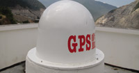 GPS Antenna at base station |
Results and Analysis
We have conducted studies using the GMAS deformation-monitoring system for the Number Two steep slope at the Xiaowan hydropower station since June 2004. The position solutions of all monitoring points were obtained based upon raw GPS data from the monitoring zone. Standard coordinates of monitoring points from the traditional surveying techniques enabled us to compare the deformation results.
We set the observation time for each antenna at 10 minutes, with the receiver-sampling interval at 15 seconds. A dedicated software package processed the data.
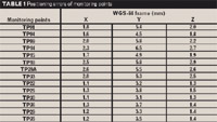 Table 1 Positioning errors of monitoring points |
Table 1 shows positioning accuracies of all monitoring points in WGS-84 frame. Table 1 shows that the positioning errors are less than 3 millimeters in the horizontal direction and are less than 7 millimeters in the vertical direction. Note that 18 survey-quality GPS receivers were required in the conventional GPS network; however, we used four survey-quality GPS receivers for our study of the Number Two steep slope at the Xiaowan hydropower station using the GMAS deformation-monitoring system.
Conclusion
We have implemented a remote-controlled GPS steep-slope monitoring system based on GMAS at the Xiaowan hydropower station and conducted a study using the system on Number Two steep slope for more than one year. The results illustrate that the GMAS system is stable and can provide precise positioning accuracy. The number of survey-quality receivers has been reduced significantly compared with the number required by a conventional GPS network.
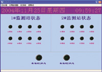 Working status of GMAS monitoring system |
Thus, the GMAS system represents an economical new technique for deformation monitoring using a large-scale network. This system is a potentially cost-effective solution for deformation monitoring of constructed and natural structures such as dams, slopes, and landslides.
Acknowledgments
This research work was supported by Grant Number 50279005 from the National Nature Science Foundation of China and the Key Project of Chinese Ministry of Education( Grant No. 104102).
Manufacturers
The GPS multiple-antenna switch developed by the authors embeds NovAtel (www.novatel.com) OEM4 GPS cards.
XIUFENG HE is a professor at the College of Civil Engineering, Hohai University in Nanjing, China.
WENGANG SANG is a Ph.D. student at the same institution.
YONGQI CHEN is chair and head of the Department of Land Surveying and Geo-Informatics, Hong Kong Polytechnic University in Hong Kong.
XIAOLI DING is a professor in the same department.
;