
With the recent introduction of cheap ΔΣ analog-to-digital converters (ADCs) offering resolutions of 24 bits or more, you'd think that the digital revolution is complete, and that the need for analog design has passed. Twenty-four bits gives you a resolution of better than 1 μV on a 10 V span, so these high-resolution converters will make it easy to solve many interfacing problems with a minimum of additional circuitry.
The transducer side of sensing, however, hasn't exactly been stagnant. New applications are placing increasingly stringent demands on recovering signals from existing transducers, and new transducer techniques are often dependent on subtle and sophisticated signal processing and recovery techniques. In many cases, micro sensors such as MEMS devices make micro signals (Figure 1), which eventually have to be boosted to levels where they can be handled by a system's ADC.
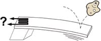 Figure 1. Micro sensors make micro signals that have to be raised to levels manageable by the system's ADC |
What's Amplification?
Amplification is the set of techniques used to boost a signal's strength. Figure 2 shows a combination of an idealized transducer and an idealized amplifier. The key features of the transducer model are an open-circuit voltage (VOCT) and an output impedance (rOT). The amplifier has an input impedance rIN, an output impedance rOA, and an open-circuit output voltage defined as VOCA = AVVIN, where AV is the amplifier's gain.
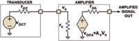 Figure 2. An idealized transducer and idealized amplifier are combined here |
Maintaining Accurate Gain
While the overall goal is to increase the amplitude of the transducer's output signal, there are a number of secondary goals that must be considered when selecting or designing an amplifier. One of the most important of these in many sensor systems is to maintain accurate gain. In the system of Figure 2, there are two fundamental ways you can achieve this.
The first is to simply make the amplifier's input impedance much higher than the transducer's output impedance. The signal seen at the amplifier's input will be VOCT × [rIN/(rIN+rOT)], which is about equal to VOCT when rIN >>rOT. For example, with transducer output impedances less than a few megohms, a simple op amp amplifier circuit such as the one shown in Figure 3 can often be used. When implemented with a suitable FET-input op amp, this circuit can provide in excess of 1010 Ω of input impedance at DC. Using a very high input impedance amplifier is often an adequate and simple solution to many interface problems.
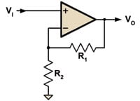 Figure 3. In some cases, a simple op amp circuit can help you maintain accurate gain |
Special Cases
In some cases, especially those involving high-frequency signals or very small signals, the high-input impedance solution may not be adequate. At high frequencies, an amplifier's input impedance may be dominated by a reactive component. For example, a FET-input amplifier that provides 1012 Ω input impedance at DC may have a 1 pF input capacitance, which appears as roughly 160 kΩ at 1 MHz. So much for the benefit of high DC impedance.
When you need to detect very small signals, one subtle disadvantage of the high-impedance approach has to do with delivery of power to the amplifier. Although we often tend to think of amplifiers as purely voltage-in/voltage-out devices, in reality they are amplifying power. And to get maximum power to the amplifier input, its impedance should match that of the transducer.
Consider a signal source of 1 μV with a source impedance of 10 kΩ. To maintain 1% accuracy requires an input impedance >1 MΩ. The total power delivered to this input impedance is roughly 10–18 W (~1 μV2 /106 - Ω). In the case where we use an amplifier with a matched input impedance of 10 kΩ, the power delivered to the amplifier is 25 × 10–18 W (1μV2 /(4 × 104 Ω)). The high-impedance amplifier is using only about 4% of the available input signal power!
Note that in order to benefit from this approach, all of the input signal must be used by the amplifier—e.g., you can't artificially reduce the input impedance by shunting signal to ground through a resistor. Doing so results in a case that uses even less signal power than the high-impedance amplifier alone.
Impedance Matching
The impedance matching approach can be valuable in the following circumstances:
- 1. You can control matching well. This usually implies that the signal is narrowband, as it can be difficult to control impedances over wide excursions of frequency. If you can't control the matching, then you can't control the system gain.
- 2. You can't control matching well, but the signal is really tiny and you need all the gain you can get. In some types of measurements, the absolute accuracy of a signal isn't that important, but the ability to detect small changes is.
One classical problem when trying to match impedances is, well, getting input and output impedances to match. The input impedance of that spiffy high-performance, low-noise amplifier is probably not going to match the output impedance of your transducer (unless the transducer impedance miraculously happens to be 50 Ω). An equally classical, yet often forgotten, solution to impedance matching is transformers. In addition to stepping voltages and currents up and down, they also transform impedance.
In Figure 4, the transformer will step up (or down) the transducer's output voltage by the ratio of secondary to primary turns (NS/NP). The AC impedance seen looking into the secondary is the transducer output impedance stepped up (or down) by the square of the turns ratio ((NS/NP)2 ). For example, if you had a transducer with a 100 Ω output impedance, and an amplifier with a 10 kΩ input impedance, a transformer with a 1:10 primary-to-secondary turns ratio would match these devices for optimal signal power transfer. The major limitation, of course, when using transformers for impedance matching is that they work only for AC signals.
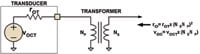 Figure 4. For impedance-matching, a transformer will step up (or down) the transducer s output voltage by the ratio of secondary to primary turns |
Bloopers Department
A number of readers noticed that Figures 4C and 4D were swapped in my July column. A few suggested that this might have been intentional and part of the "Final Exam." As much as I would like to run with this suggestion, I am nowhere near that clever—it was indeed a mistake. Thanks to all of you who noticed this and pointed it out!
Ed Ramsden, BSEE, a member of the Sensors Editorial Advisory Board, designs sensors for the heavy-truck industry in Portland, OR.