
Our mobile robotic platforms are fully autonomous—they drive themselves from place to place, safely avoiding obstacles (including people and pets) encountered along the way. Their advanced path-planning and mobility systems do not use external guidance systems, artificial paths, or special targets to navigate the workspace, eliminating the expensive retrofitting and installation common in today's automated-vehicle applications. The same versatility also allows the robot to go to any place accessible in the workspace, rather than being restricted to prescribed paths or to set goals. Moreover, the robots adapt to their workspace—especially to dynamic spaces such as a hospital ward—modifying their drive path as needed to "get there from here" automatically and reliably, without the need for human intervention (Figure 1).
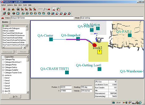 Figure 1. The MobileEyes GUI monitors the robot's progress and displays operating conditions, including onboard sensor readings |
Sensors play critical roles in our intelligent robotics. Some are simple; some quite sophisticated. Many are essential, such as those used for localization and navigation—key features that enable autonomous mobility.
Onboard interfaces and enabling robotics software also provide the means for integrating and managing sensor payloads to provide an alternative to mesh networking and manual sensor data collection. These technologies are collected into the company's Advanced Robotics Control System (ARCS). In addition to building their own robot applications, MobileRobots licenses the technologies to OEMs for use in their own ARCSinside robots.
Mobile Robot Basics
To understand the various roles sensors play within a mobile robot, we'll discuss the various types involved: those used for odometry, those used for rotational measurements, those used for ranging, and finally those used for proprioception, which measure objects and conditions such as operating temperatures near and inside the robot itself.
Odometric Sensors. Most of the company's robots, such as the PatrolBot and the Pioneer-AT platforms, employ two-wheel differential or four-wheel skid-steer (tank-like) drive systems. Seekur, the new outdoor mobile platform employs a four-wheel, independent steering and drive system to achieve holonomic mobility (the ability to turn and move in any direction). At the lowest level, a microcontroller with firmware and sensors provides for driving and steering the robot. Encoder inputs and motor-control outputs provide the motion-control feedback loop.
Precisely timed interrupts within the real-time operating system on the microcontroller provide a base for precision wheel speed and travel distance calculations. Accumulated ticks from the encoders are used for position integration and, consequently, localization and navigation. For mobile robots, the distance traveled by each wheel is typically combined into translational and rotational components which, from basic geometry, ultimately provide position and heading. For example, with encoder-based differential-drive robots moving in 2D space (a typical flat floor indoor environment), position integration begins by accumulating the translational (D) and rotational (R) partials, measured as the change in encoder readings for each side, left (ΔEL) and right (ΔER), at precise time intervals (t). D is then given by Equation 1.
| (1) |
where:
| (2) |
Similarly, R is given by Equation 3:
| (3) |
where:
C = differential number of encoder ticks, right vs. left, for radians.
dR = ΔER – ΔEL
Heading in degrees (θ) is computed using Equation 4:
| (4) |
where:
ω = wheelbase length between where each tire meets the drive surface.
Consequently, we see in Equation 5, the platform's 2D (X,Y) position coordinates are:
| (5) |
Trajectory and motion-control algorithms, which compare progress of the robot against pre-set speed and (de)acceleration goals for both translation and rotation, close the feedback loop. The algorithms adjust the pulse-width-modulated (PWM) output signals that ultimately increase or decrease power to the drive motors after applying a common PID process to achieve smooth performance.
Error—a fact of life in the real world of robots—is principally due to platform and terrain imperfections, e.g., the roundness of the tires and wheel slippage. Error accumulates rapidly and rotational error affects platform odometry dramatically. For example, a 1° imperfection in the heading means the platform will drift off-course nearly 700 mm for every meter of travel.
Rotation Sensors. For more reliable rotational measurements, the platforms typically use rate gyroscopes. The robot's heading is computed from the accumulated changes in rotational speeds at a set time period and consequently used for position integration and to correct the platform's odometry.
Currently, the robots use only rate gyros for correcting rotation and use simplified schemes for gyro-compensated odometry. Future configurations may integrate inertial measurement units (IMUs), tilt-roll, and triaxial inertial sensors, particularly in Seekur, to measure and compensate for the many real-world conditions that confound the odometry, especially on hilly and rough outdoor terrain. The advanced algorithms provided by Kalman filtering, which extract an erratic signal from noise, also may be used to refine and fuse the various mobility-related sensor inputs into better odometry.
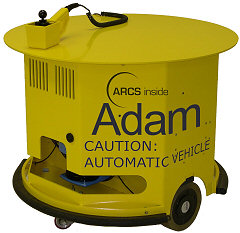 Figure 2. ADAM carries up to 250 lb payload in industrial applications |
All of the company's R&D and commercial robots support SONAR, and use it for obstacle detection. The small robot for education, AmigoBot, has eight ultrasonic sensors around its perimeter for nearly 360° of coverage. For practical robotics, SONAR's 8° cone of operation detects reflective objects out to a useful maximum of around 5 m (~16 ft.). Its drawbacks include a very weak signal and a limit on the robot's speed, as even a slowly moving mobile platform will have moved significantly out of the echo's path for any longer time-of-flight. Cross talk between one or more transducers due to platform motion also seriously confounds its ability to perceive distant objects.
The precision of a scanning laser rangefinder is some 25 times that of SONAR—0.5° increments over 180° with ±1 cm error—even though data acquisition times are nearly the same for the same coverage (around 120 ms per 180° sweep). The SICK Optic LMS200 is the ranging sensor preferred for most research and commercial robotics because of its precision and its rugged case. Its laser beam is highly focused and not readily distorted or absorbed by the reflecting medium, so the precision of range finding with the laser is superior to SONAR with far fewer false-positive readings.
Because the time-of-flight is nearly instantaneous, the laser can more reliably sense objects at a greater distance (up to 50 m; 164 ft.) from the moving platform. Since rooms and commercial spaces commonly are eight or more square meters in size, a SONAR-based robot can easily get into voids where reflecting objects such as walls are outside its detection limits. Without feature clues, navigation becomes imprecise; the robot is lost in space, so to speak.
Although the laser's precision and range enable nearly errorproof localization, one disadvantage is its scanning height, a thin plane less than 1° high. SONAR's cone of operation provides broader sensing for proprioception, such as acute obstacle avoidance, and this is why the robots operate best when equipped with both sonar arrays and a laser.
The LMS 200 is also heavy, power-hungry, and expensive. "Weight is the most important characteristic from a mechanical point of view," says Seth Dunten, Senior ME for MobileRobots. "Sometimes we would like to mount the laser up high to detect features like windows, but a ten-pound device four feet above the floor is awfully hard to stabilize on a base the size of PatrolBot." PatrolBot has a 48 cm wheelbase, is 59 cm front to back, and can support a 46 kg max. payload. To date, MobileRobots has been unable to find a lighter rangefinder or one with a broader sweep that performs adequately.
Proprioception Sensors. Depending on the application, some of our robotic platforms come equipped with IR sensors—either break-beam or ranging—for close (<1 m) obstacle detection. These provide a measure of protection for payloads and accessories that are mounted to the platform outside of the SONAR- or laser-sensing envelopes. Bumpers, too, provide a measure of obstacle detection, albeit as a last resort.
Strategically placed thermosensors provide additional proprioception for the onboard systems. Combined with watchdog firmware, these sensors will effect a shutdown should critical components, such as the battery or computer, overheat. Charging control electronics rely upon an array of sensors to measure voltage, current, and coulombs of energy in and out. Automated charging systems allow the mobile robots to operate autonomously for months on end without the need for attention or maintenance.
Localization and Navigation
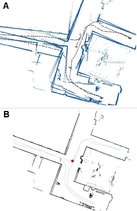
As mentioned earlier, laser-based techniques are used to locate the robot in its workspace. Using probability algorithms, readings from the LRF are compared with readings from an initial building scan collected during the robot installation process. This initial scan, performed by manually driving the robot around the workspace with a joystick, is converted into an "occupancy grid map," showing which parts of the floor plan the robot encountered, such as walls and other objects. Since the robot's location is constantly updated, there is no cumulative error.
With these three types of sensors—odometric, ranging, and proprioceptive, the robots safely travel around buildings with amazing repeatability. They find their charging stations and dock themselves. They deliver everything from tiny hospital specimen bottles to large auto parts (Figure 3). In fact, at MobileRobots' headquarters, you can call a robot to bring you a soda, cooled in a miniature refrigerator on the robot's back. "Get your sodas! Get your sodas here!" it cries. If someone steps in its way as it's heading toward your office, SodaBot won't stop to let him grab a drink. Instead, it will use its laser sensor and occupancy grid to determine dynamically the best path around him and continue on toward its thirsty customer. Now that's intelligent sensing!
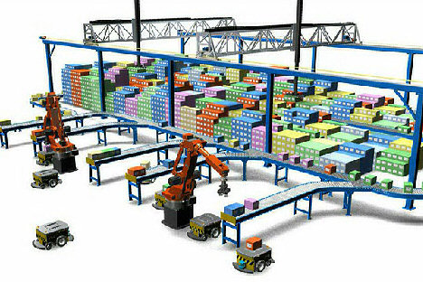 Figure 3. MobileRobots' intelligent, versatile platforms can play an essential role in larger parts delivery systems |
|
ARCinside, PatrolBot, Seekur, MobileEyes, and MobilePlanner are trademarks of MobileRobots Inc.