
 The control of fluid power has changed dramatically over the last 20–30 years. The pressures needed in this industry today—5000 or 6000 psi—are double what they were in the late 1990s. These high pressure requirements bring with them a higher risk of employee injury or downtime.
Market Forces
Hydraulic cylinders are used in many industries, but to avoid the damage and disrepair caused by their heavy loads we need to control their deceleration. Past methods have included shock absorbers, which take up a lot of space; proportional valves, which are expensive and wear down with environmental and vibration erosion effects; and a cushion designed into the cylinder, which brings the load to a gentler halt as the cylinder reaches its end of stroke. With advances in electronics and the ability to integrate electronics with hydraulics, use of hydraulic cylinders continues to grow. Manufacturers are embedding sensors in the hydraulic chassis and creating designs to interface directly with standard electronics controllers.
A key issue is the need for increasingly higher operating pressures. The mobile hydraulics segment accounts for about half of the fluid power industry (a $13.5 billion market in 1998). This segment is the most volatile, expanding and shrinking more than any other segment; it is expected to continue expanding as the global demand for capital equipment increases due to the rebuilding of infrastructures in Eastern Europe, Asia, and South America. The Department of Agriculture projected 5.5% growth through 2006 with 20% of this in cylinders.
End-of-stroke is one of the most important signals to be monitored in a hydraulic system. Originally monitored by mechanical means, this signal allowed the hydraulic designer to determine when the cylinder had completed its motion in a given direction. The shortcomings associated with mechanical switches include their short life cycle, the need for constant readjustment, susceptibility to damage from external forces, lack of precision and low repeatability in switch points, and accidental actuations. Their strengths include low initial cost and the fact that they are outside the hydraulic system and therefore unaffected by pressure.
Pressure-Resistant Switches
Pressure-resistant inductive proximity switches are used in a multitude of applications, including hydraulic systems with pressures up to 7250 psi. Pressure resistance requires thick housing walls, particularly at the sensing face. The main problem then becomes how to provide an acceptable operating distance in spite of the thick walls.
Reinforced Housings. These proximity switches attain the required pressure resistance by using sufficiently strong walls. At the sensing face, a ceramic disk—with sufficient thickness to withstand pressure without needing further reinforcement—is used inside the housing. The electronics module, including the ferrite core and the coil, is placed in the pressure-free part of the housing. Because of the thickness of the ceramic disk (2.5 mm for
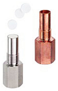 Figure 1. The housing and the ceramic disk before and after assembly |
Sealing the Sensing Face. Pressure resistance, by necessity, demands a seal that prevents harmful quantities of liquids and gases from entering the housing, even at maximum operating pressures. Such a seal is particularly crucial between the ceramic sensing face and the metal housing.
In the case of new-generation proximity switches, the housing is heat shrunk onto the ceramic disk. Figure 1 shows the housing and the ceramic disk before and after assembly, and Figure 2 shows the parts in cross section. Assembly is made by inductively heating the housing in the joint area. While the housing is still hot, the ceramic disk is inserted, and the assembly is left to slowly cool down. Due to the metal's higher temperature coefficient, as compared to ceramic, the metal housing shrinks far more than the ceramic disk. With the appropriate choices of diameters d1 and d2, this results in a powerful force fit—up to 200 N/mm2 at the interface.
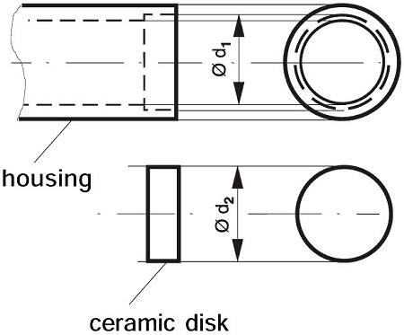 Figure 2. A cross-sectional view of the housing and ceramic disk |
Still, the fit is not yet sufficiently impervious. It requires gas-tight sealing, where a thin layer of copper is inserted between the housing and the
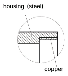 Figure 3. Gas-tight sealing |
Operating Distance. A large part of the usable operating distance is lost due to the thickness of the ceramic disk. Therefore, to achieve a sufficient operating distance, we use an electronic module with an operating distance approximately 3 times the norm, instead of the standard module. For the P20, the resulting operating distance is 3 mm.
Dynamic Requirements. Conventional pressure-resistant proximity switches are rarely suited for dynamic pressure requirements because their support systems and Teflon seals wear out after a limited number of pressure cycles. In practice, this kind of strain occurs frequently, especially in hydraulic systems. New-generation proximity switches, due to their simple construction and in conjunction with the high pressure used to bond the housing onto the ceramic disk, are completely insensitive to dynamic strain and pressure peaks. Their advantages include:
- A virtually unlimited number of pressure cycles permissible over the full range of pressure
- Long operating distances
- Gas-tight at the sensing face
- Easy to mount
- No setting required
Applications
The newer pressure-resistant proximity switches can replace devices currently available on the market. While their easy mounting and their longer operating distance are important, they are particularly suited to applications where dynamic pressure strain is to be expected, such as:
- Piston end-of-stroke (end position) monitoring in hydraulic cylinders
- Control and monitoring of hydraulic valve switching
- RPM monitoring and measuring of hydraulic motors
- Control and monitoring of valve switching in gas distribution systems (the devices are gas-tight)
- Applications in high vacuum
Looking Forward
As the hydraulics industry continues to advance, higher pressures are being used in more applications. When end-of-stroke signals are required, a switch located in the end cap is the most reliable sensing choice. The sensor industry has evolved to produce reliable end-of-stroke sensors that can operate in today's high-pressure environments, with safety margins approaching 40%.
A variety of configurations are available today to meet a broad range of high-pressure applications (Figures 4 and 5).
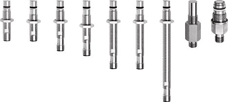 Figure 4. Some of the main choices of high-pressure quick-connect switches available |
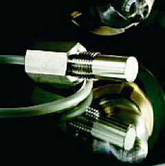
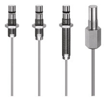 Figure 5. High-pressure switches are also offered with integrated cables |
To see more complete technical data visit www.contrinex.com and click on "technical info."