From making your favorite characters at Disney wave hello, to surviving the extreme conditions in downhole drilling operations on earth, satellites, guided missiles, and even the surface of Mars, potentiometers are used in every imaginable system that requires infinite resolution for both control and position sensing. Current technological developments are pushing potential applications even further.
Potentiometers—simple electromechanical devices that translate rotary or linear motion into a change in resistance—have been a cornerstone of measurement, control, and position systems for more than a century. In a potentiometer, one terminal is hooked up to a voltage source and the second to ground. A third terminal connects a sliding contact called a wiper that runs across a resistive track. As the wiper is moved across the resistive track, the voltage changes, corresponding to the new position. This voltage change can be used to control anything from volume or light intensity to the movement of complex mechanical systems. These three-terminal resistors with a sliding contact form an adjustable voltage divider, current divider, or other devices. When only two terminals are used (one side and the wiper), a potentiometer acts as a variable resistor or rheostat.
Until recently, it was believed that potentiometers might be pushed aside in favor of digital devices such as encoders and resolvers. However, technical advances have improved potentiometer characteristics and these improvements, coupled with the potentiometer's inherent advantages, mean that potentiometers are now proving their merit in the most advanced space, aerospace, and medical applications.
Before delving into the pros and cons of potentiometers versus some of the new digital technologies, it is important to have a basic understanding of the specifications that can be tailored to meet the requirements of specific applications. They are as follows:
- Mechanical specifications—Potentiometers can be designed to fit a variety of custom packages and interfaces. Special design considerations will take into account package size (length and diameter), shaft configuration, torque, mechanical travel, stops, radial and end play, mounting, and termination requirements.
- Element designs—The resistive tracks can be made from a variety of substrates, based on the user's requirements for mounting, environmental conditions, and product lifespan. Potentiometers can be either rotary or linear and can be mounted in housings or integrated into the user's subassembly, such as within a motor housing.
- Life—The life of conductive plastic potentiometers is typically >5 million cycles. Life can be extended through the use of lubricants and by using different types of precious metals to form the wipers.
- Resistance—Potentiometer resistances can be tailored to meet the needs of the applications. The carbon mixtures that are deposited on the substrates can be custom mixed and will hold tolerances as low as 1%.
- Resolution—Resolution is characterized as the minimal amount by which the voltage changes in response to a corresponding shaft movement. One of the biggest advantages of potentiometers is that the resolution is virtually infinite. In feedback or position systems this infinite resolution eliminates the need for system hunting, which often results in jitter, and also allows for larger gains (i.e., clean amplification) in amplifier circuits, and a better frequency response. A potentiometer is an absolute position sensing device. As such, when powered on or off, the potentiometer always knows where it is positioned and does not need to return to zero, as is the case with other incremental position sensing devices.
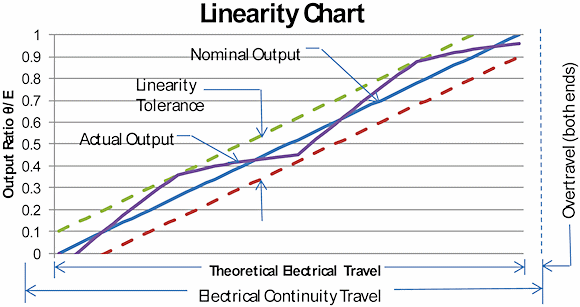
- Linearity—The key specification of most potentiometer designs is linearity, which is defined as the proportional difference between the actual output voltage and a calculated voltage based on position (Figure 1). Linearity tolerance depends on the length or function angle, the total resistance, and the size of the tracks. The greater the angle and track size, the lower the resistance, and the better the accuracy that can be achieved. Linearity can be specified in one of two ways: either absolutely or independently.
 Figure 1. A graph of linearity (max. deviation) |
- Absolute linearity takes into account the actual electrical angle of the potentiometer. Potentiometers have a certain degree of angular variation; tolerances can vary from as little as 0.01° to as much as 2° depending on size, angle, and element material. From this angle a table can be computed based on position of the shaft.
- Independent linearity does not take into account the actual angular variation of the potentiometer (there is no function angle tolerance). Instead, it uses a table, based on the desired angle, to compute the required slope and then determines the variation at a given shaft position.
- Functional Linearity—Linearity can be specified for either a straight line or for a variety of functions. These functions are most commonly sine/cosine, logarithmic, or multislope. However, output requirements can be tailored to a specific function as needed. No additional support circuitry is required to create these functions, in contrast to other digital or magnetic-based technologies.
- Resistive Loading—Resistive loading alters the theoretical output function of the potentiometer and can occur in three different ways:
- Between the wiper and the end tap
- Between the wiper and the center tap (floating)
- Between the wiper and the center tap (grounded)
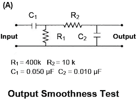
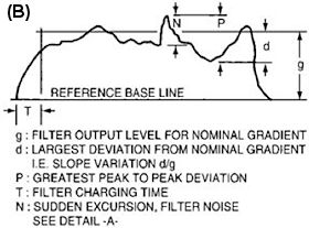
- Output Smoothness—Output smoothness (Figure 2) represents the maximum instantaneous variation in output voltage with respect to the input voltage and is measured while the wiper is moving and an input load current is present. This value is expressed as a percentage of the total applied voltage when the potentiometer is rotated at 4 RPM. The factors that influence output smoothness are the contact resistance and anomalies in microlinearity. (See MIL-PRF-39023; Resistors, Variable, Nonwirewound, Precision General Specification for; available at www.assistdocs.com.)
- Noise—Noise is caused by variations in the output, caused by transient resistances between the wiper and the resistive element surface, that do not exist in the input. (See MIL-R-12934; Resistors, Variable, Wire-wound, Precision General Specification for; available at www.assistdocs.com.)
- Power Rating—The power rating is the maximum power that can be dissipated by the potentiometer, assuming it is acting as a voltage divider rather than as a rheostat. The rating is usually stated at ambient temperature and should be de-rated for potentiometers operating at higher temperatures.
- Environmental factors—When specifying a potentiometer, the conditions under which the potentiometer will perform are critical and include conditions such as high and low temperatures, moisture, vibration, and shock.
 Figure 2. Output smoothness (spurious variation) |  |
A Technology Comparison
The table in Figure 3 compares the different types of control and position sensing technologies available, based on their resolution, accuracy, power consumption, power loss conditions, and external support circuitry.
Encoder basics. Encoders transform mechanical rotary motion into a sequence of electrical pulses that are monitored for display or control functions using a counter, display, PC, PLC, tachometer, or controller. In principle, absolute and incremental encoders are similar, in that a rotating disk interrupts a photodetector to produce an output signal.
In incremental encoders, the rotating disk contains a single track of evenly spaced clear and opaque segments. With one pulse track on the disk, incremental encoders deliver on/off outputs that provide speed and directional data to a monitoring or control device through the quadrature output. In standard mode, an encoder counts the leading edge of one square wave signal. By counting both the leading and trailing edge of the signal, resolution is doubled. For higher resolution, some encoders replace square wave signals with sine wave outputs that allow for interpolation. Absolute encoders use a more complex method to encode the disk, allowing for greater accuracy and placement recovery after power loss.
LVDT basics. A linear variable differential transformer (LVDT) converts the linear motion of an object to which it is mechanically coupled into a corresponding electrical signal. The LVDT consists of a primary winding centered between a pair of identically wound secondary windings. The moving part is called the core, which is free to move within the LVDT's hollow bore, and is mechanically coupled to the moving object. In operation, the primary winding is energized by the appropriate amplitude and frequency. The LVDT's output signal is the differential voltage between the two secondary windings, which varies with the axial position of the core within the LVDT coil. This output voltage is then converted to a high-level DC voltage or current that is more convenient to use.
Figure 3. Comparison table of position sensing technologies
| Characteristics | Potentiometer | Encoder | LVDT |
| Cost | Low | Moderate to High | Moderate to High |
| Linearity | <0.1% | N/A | Dependent on winding configuration |
| Function | Can be trimmed to specific functions | Can be manipulated by software vs. position | Can be wound into unit, limited to variation in turns |
| Power Loss Recovery | Position recovery is simple; units power up at previous voltage | Position recovery is somewhat complex, relying on a stored previous position or on re-indexing of the system | Position recovery is simple; units power up at previous voltage |
| Resolution | Infinite | Depends on size, support circuitry, and cost | Infinite (limited by noise in the LVDT signal conditioner) |
| Power Consumption | Low | Depends on size, support circuitry, and cost | Moderate to High |
| Overhead Support | Low | Moderate to High | Low |
| Life | > 5 million cycles | 10 million cycles | >10 million cycles |
Potentiometers are more cost effective than the alternative technologies, especially when tight resolution and linearity requirements are an important factor in the design.
One of the primary characteristics to consider when selecting a sensor is how the system recovers after a power loss. In the case of potentiometers, the system has no need to reposition to an origin or index mark; it will provide the output voltage that corresponds to its current position. In the case of digital devices, the system has no real method to determine its current position unless it re-indexes or returns to an origin. Unfortunately, in most system applications, returning a system to a position other than its current position is impractical and takes both power and time. Furthermore, it may not be possible to reposition the system if doing so can affect the current mission-critical parameters.
Infinite resolution is another primary advantage of potentiometers over other digital devices. If the application you're designing cannot tolerate a step-type output, then potentiometers are the appropriate technology to use. While digital devices have greatly increased their resolution, this improvement involves a tradeoff. Generally, in order to achieve higher resolutions, digital devices require much space, power, and overhead to support them but cannot match the potentiometer's infinite resolution. Just ask any audiophile with a high-quality mixing board; incremental slide potentiometers provide a precision that cannot be duplicated using a digital device.
Potentiometers consume very little power. Coupled with the power required for overhead support, potentiometers provide savings in power consumption, space, and weight. In applications where multiple devices are required, this advantage is multiplied.
One theme of the modern age is to do more in less space and at a lower cost. Potentiometers shine in this area. They require less bulky support hardware and software and, because positioning is determined by reading an output voltage, there is no need to determine the direction of rotation or movement, and therefore no need to keep track of a current position with ancillary hardware.
Potentiometers can be packaged to meet most customers' envelope specifications (e.g., diameter, length, shaft requirement, etc.,) without sacrificing resolution or linearity. Although encoders and LVDTs can be configured to meet these mechanical specifications, it often comes at a cost; as encoders get smaller, resolution is compromised and as LVDTs get longer, they become more expensive and their linearity is compromised for very long lengths.
Any devices—potentiometers or other technologies—that are to be used in dirty environments or relatively high humidity must be sealed to prevent microscopic particles from infiltrating the device. In the case of potentiometers, a small particle may cause a dead spot in the active region of the track, but in most cases, the system can tolerate one such spot and still function effectively. For optical devices, particulate contamination may cause erroneous readings in the position count.
Degradation at temperature extremes affects potentiometers to a greater degree than it does their digital counterparts. However, in most cases, the temperature extremes required to cause degraded performance are well beyond the temperature requirements of the system.
Many of today's systems require redundancy, with one section used for position control and the other used for feedback. While both potentiometers and encoders are capable of this, potentiometers simplify the task. Comparing voltage outputs requires minimal support hardware, and redundancy in potentiometers can be accomplished by either having multiple potentiometer sections or multiple tracks within the same section. This consideration is critical where cost, space, and power consumption are important.
Although noncontacting digital devices have historically surpassed potentiometers in terms of usable life, potentiometers today have life cycles that exceed 5 million cycles, far beyond the requirements of most applications.
In evaluating the potentiometer among other sensing devices, all of these factors need to be weighed against one another to select the appropriate technology for your application.
The Future
Betatronix was an early pioneer in the potentiometer industry. Today, it is leading the way in developing new technologies and advancements, including the conversion from manual trimming (a method of improving linearity tolerances by cutting carbon or applying silver to the surface of an element) to computer controlled, fully automated laser trimming, resulting in devices with significantly improved linearity specifications and improved stability over wider temperature ranges.
Currently, Betatronix is working with several companies to develop a process that moves away from the standard methods for depositing carbon and toward more streamlined and modern processes. The expected results are improved yields, improved performance, longer life, and reduced noise.
The potentiometer has been the workhorse of control and position systems for over a century. Advancements in potentiometer manufacturing have made them more reliable, more accurate, and more cost effective than ever before. When making technology choices for your future designs, potentiometers should be part of your evaluation process. Recent developments in manufacturing have enhanced their overall performance without compromising their inherent advantages and may yet make potentiometers the new "new thing."
ABOUT THE AUTHORS
Brian Rosengrant is Director of Quality Assurance and Engineering for Betatronix LLC, Hauppauge, NY. He can be reached at 631-582-6740 or [email protected].
Bill Kostik is Manufacturing Engineer for Betatronix LLC. He can be reached at 631-582-6740 or [email protected].