
When Michael Faraday introduced the concept of an electric field, little did he realize how far science would run with the idea. Today, engineers are using electric fields to sense the presence of other objects without relying on physical contact. Referred to as e-field sensors or capacitance sensors, they are becoming more and more prevalent in a wide range of inexpensive and long-lasting applications. When you take a closer look at how they work, you quickly see why their popularity is growing.
Capacitance Sensors in Theory
Capacitance sensors exhibit a change in capacitance in response to a change in physical stimulus. Certain capacitance sensors measure the change by generating an electric field and measuring the attenuations suffered by this field. Unlike inductive sensors, which can detect only metallic objects, a capacitance sensor can detect anything that is either conductive or has dielectric properties different from the sensor's electrodes' surroundings. Coincidentally, this makes human beings very good candidates for e-field imaging, because, being mostly water, we have a high dielectric constant and we contain ionic matter, which makes us good electric conductors.
Oscillator circuitry in the sensor integrated circuit (IC), such as the Freescale MC34940 e-field imaging device, generates a high-purity, low-frequency 5 V sine wave, tunable by an external 39 kΩ resistor. This AC signal is fed to a multiplexer that directs the signal to a selected electrode (the MC34940 supports seven) or reference pin, or to an internal measurement node. The IC automatically connects the unselected nodes to the circuit ground, and these act as the return path needed to create the electric field current.
When an object is brought close to a metal electrode—for instance, a finger from our highly dielectric and conductive human subject—an electric path is formed, producing a change in the electric field current. The sensor measures the AC impedance of the generated e-field and translates that measurement into a DC output voltage (Figure 1). An external microcontroller can then process this information to perform any number of functions, such as those that are associated with a touch pad control panel. Capacitive touch sensing is favored among designers due to increased reliability (no moving parts), greater design freedom, and a more contemporary look.
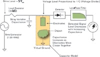 Figure 1. The Freescale MC34940 e-field imager design |
This method of measuring the AC impedance provides a more accurate reading compared to other methods, such as measuring the period or frequency of an RC oscillator. Also, by generating a pure sine wave rather than a square wave, signal interference is much less of a problem.
Capacitance Sensors at Work
Capacitance sensors can be found in a wide variety of industrial and consumer products: PC peripherals, health care patient monitors, refrigeration frost sensors, point-of-sale terminals, and garage door safety sensors.
Some of the most popular and easy-to-spot applications are touch screen and touch panel solutions. When developing a touch panel solution, keep three important considerations in mind:
- 1. The touch pad electrode design and layout
- 2. The different dielectric materials for the surface of the panel
- 3. The effect on e-field measurements of various environmental conditions
The relationships among these three considerations are described in Figure 2.
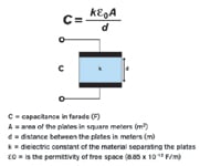 Figure 2. The relationship between touch panel design factors |
The interaction between electrode size and spacing affects the electrode's ability to sense objects in the third dimension (Figure 3). Larger electrodes have greater range and sensitivity; however, they are more susceptible to interference, electrical noise, and stray electric-field paths in their surroundings. Similarly, a greater space between the electrodes generates a larger e-field but weakens the signal. For touch panel applications, the touch pads need only accommodate the tip of a finger, limiting the usable size of the electrodes and the spaces between them.
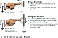 Figure 3. Single electrode versus multiple electrode touch sensors |
The effectiveness of the dielectric materials used for the surface of the panel relies on its thickness and its dielectric constant. Generally, the insulator over the touch pads should be as thin as possible with as high a dielectric constant as possible. However, the dielectric constant of a thick pad covering may increase as it is compressed, which means neoprene rubber, for example, may actually provide more sensitivity than would normally be expected.
You must also consider environmental effects when designing a touch panel application. Whereas oil from the fingertip is not likely to have a significant effect, water can affect adjacent touch pads, probably due to the higher current path from the finger to the other electrodes provided by the water's high dielectric constant. Wider separation of the touch pads can mitigate the effect, and designing the application so that water does not collect on the touch pads can also help, particularly for outdoor applications.
As touch panel displays age, temperature and humidity can eventually degrade capacitor performance. You can compensate for this with the design of the capacitance sensor. For instance, Freescale's MC33794 e-field sensor relies on two reference inputs, one connected to a capacitor with a capacitance near the expected maximum while the other is connected to a capacitor with near the expected minimum capacitance. These reference capacitances can be used to correct environmentally induced errors in the electrode measurements or other component-related changes.
A less obvious but equally well-suited application for capacitance sensors is in liquid level sensing. For example, a simple design using e-field sensing for measuring liquid levels involves placing vertical electrode strips across a water column, thus forming a vertical capacitor between the walls of the water column. An empty column forms a single capacitor. When you introduce water, you split the capacitor into two: One is filled with air (dielectric of 1) and the other with water (dielectric of about 80). Using a simple algorithm you can determine the liquid height. Unfortunately, in an application such as a washing machine, this system cannot compensate for different dielectric properties in the water as detergent is introduced and soil and other impurities begin to appear.
A more sophisticated capacitance system uses gradient electrodes; this arrangement involves two plates of equally varying thicknesses overlapping each other. As the liquid rises, different areas of the electrodes are in "contact" with the water and you can extract a unique ratio between them. The ratio is directly related to the liquid level, while the absolute values of the area provide dielectric information that you can use to estimate soap and dirt content in the water.
A third common use of e-field sensing relies on its ability to detect the proximity of an object. The capacitor model equation (Figure 2) demonstrates that the capacitance is inversely proportional to the distance between the two capacitor plates (1/d). In a typical application, a conductive electrode pad will be one plate of the capacitor; the desired object will act as the other capacitor plate.
Because the relationship between the distance and the capacitance is asymptotic, this type of sensor is better suited in applications for which you need high resolution in close proximity (Figure 4). In typical room environments, Freescale's MC34940 is able to detect a hand at 12 in. using a 1 ft. sq. pad as an electrode. Typical applications that can benefit from this technology include access control, safety, security, and wake-up on proximity solutions.
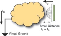 Figure 4. Diagram of a proximity sensor |
Multiple Electrodes and Shield Drives
E-field sensors, such as Freescale's MC33794 and MC34940, can support multiple electrodes, providing a platform for several applications controlled by one chip, even if those applications are widely spaced. As the electrode signals are transmitted through wires or coaxial cable to the sensor IC, however, they can be weakened by external interference. To minimize this interference, Freescale incorporated a shield driver in each of these parts.
The shield driver circuit provides a buffered version of the electrode's returned AC signal. Because it has nearly the same amplitude and phase as the electrode signal, there is little or no potential difference between the two signals, thereby canceling out any electric field. In effect, the shield drive isolates the electrode signal from external virtual grounds, resulting in remote electrode measurements as accurate as if they were in close proximity to the IC (Figure 5). A common application is to connect the shield driver to the shield of a coaxial cable used to connect an electrode to the corresponding electrode terminal.
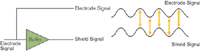 Figure 5. Diagram of a shield drive |
Another typical use for shield drive technology is to drive a ground plane used behind an array of touch sensor electrodes to cancel out any virtual grounds that could weaken the AC signal (Figure 6). The shield drive limits signal losses to the fringe field, thereby helping to ensure the strongest potential e-field. In a touch panel, for example, this increases the touch pad's sensitivity.
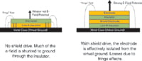 Figure 6. Results without and with a shield drive |
Shield drive technology allows developers versatility. It can drive a number of separate applications using a minimal number of e-field sensor ICs (the MC33794 supports nine electrodes and the MC34940 supports seven). Additionally, it can be used to design large arrays of separate electrodes to perform identical functions over a wider area, such as smart floor mats that can sense occupants and even track their movements.
Combine e-field sensing with a wireless protocol, such as ZigBee technology, for expanded control and tie-in to a local area network, and the application opportunities are practically endless. Safety, security, lighting, integrated entertainment controls, and general proximity detection are just a few applications that can take advantage of the convenience and relatively inexpensive characteristics of e-field sensing technology. Michael Faraday would surely be impressed.
Philip Sieh, MSEE, and Michael Steffen, BSEE, can be reached at Freescale Semiconductor Inc., Austin, TX, 512-895-2000, [email protected] and [email protected], www.freescale.com.