

Logging linear movement can be a complicated and expensive business. A variety of measuring systems can be used, depending on the accuracy required and distance to be measured. The simplest of these is the sliding potentiometer, which supplies a variable resistance proportional to the distance of travel. Incremental or absolute linear encoders can have accuracies of <1 µm at lengths of several meters. Simple applications, such as level controllers, lift magnets, seat adjusters, motion sensors, or noncontact sliding switches, however, require the measurement of distances from a few millimeters to several hundred centimeters—as inexpensively as possible and without contact between the components. Magnetic encoders based on Hall sensors have long been successfully deployed for the detection of rotational motion [1].
The operating principle of rotational magnetic encoders is based on detecting the magnetic field of a cylindrical, diametrically magnetized permanent magnet positioned normal to the IC. The four Hall sensors measuring the rotating magnetic field are arranged in pairs orthogonally. These provide suitable electrical sine and cosine signals from which the angle of rotation of the permanent magnet can be clearly derived. For sensing linear position, the new iC-ML has the four Hall sensors placed in a line and configured for a magnetic pole pitch of 2.56 mm. The circuit allows a suitable magnetic tape of any length to be used and also permits error-free assembly, thus reducing the time and effort required for this part of the production process.
iC-ML Details
Figure 1 shows the iC-ML in relation to the magnetic tape. The X coordinate lies in the direction of the tape's orientation, which alternates between north and south magnetization, and parallel to the chip's surface. The sine and cosine signals shown are the electrical output voltages in analog operating mode. The origin of the magnetic tape coordinate system is set to the center of any one of the north poles.
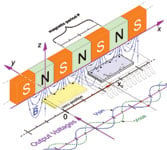 Figure 1. The principle of magnetic position sensing using integrated Hall sensors |
Mechanically, the iC-ML's longitudinal shift is then defined by the distance xd between the outermost Hall sensor on the left and the origin of the magnetic tape. If the circuit is moved along the X axis, the signal pattern shown in Figure 1 is generated at the device outputs. With each magnetic period of 5.12 mm an electrical signal period is produced. Within this period the absolute position can be determined.
The circuitry integrated into the iC-ML contains a Hall signal amplification unit with automatic gain control, compensation for changes in temperature, magnetic field strength, and supply voltage, as well as an A/D and a D/A converter for digitized and converted analog output signals. The differential magnetic field evaluation makes the circuitry insensitive to external magnetic DC fields. If the magnetic field strength drops below an acceptable threshold, depending on the configuration of the iC-ML this is either shown as an analog value (GAIN output) or digital signal (NERR output).
The signal conditioning unit of the iC-ML supports a resolution accuracy of 20 µm at a linear speed of up to 5 m/s. In addition to the sine and cosine signals, which are kept at a constant amplitude of 2 Vp-p, the IC provides digital signals in the form of incremental pulses and ABZ quadrature signals with resolutions of 6, 7, and 8 bits per magnetic period. A further option is to generate sawtooth and triangle signals by converting these digital signals back to analog.
Modes of Operation
Various modes of operation are coded in tri-state logic via three inputs. The three states are low, high, and Vcc/2 level, which sets itself automatically with an open input. A total of 26 operational modes can be selected using the three inputs:
- 1. Analog sine and cosine signal (unipolar or differential)
- 2. Incremental A/B signals with a zero pulse
- 3. Counter pulse for up/down binary counters
- 4. Analog sawtooth or triangle signal with a settable amplitude
Using the iC-ML in a System
A complete linear measuring system can be created using a magnetic tape as a material measure and an iC-ML. Figure 2 shows one example of the way this measuring system can be connected to a microcontroller. In this setup, the iC-ML is configured as a linear sensor and outputs analog signals equivalent to those in Figure 1, PSIN and PCOS, both of which must be referenced to REF. The GAIN signal acts as a measurement of the available magnetic field strength and can be used to detect errors, such as a missing magnetic tape or one placed too far from the sensor.
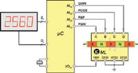 Figure 2. Linear position sensing with a microcontroller |
The configured mode of operation is accepted when the iC-ML is activated by the microcontroller with a low at the NEN input. With pins CFG1, CFG2, and CFG3 wired to ground, iC-ML's I/O ports A, B, C, and D, which are initially neutral, are configured as outputs with the characteristics in Figure 2.
The iC-ML supports the measurement of linear position on several channels or axes with the use of three cascade modes. This entails connecting several devices in a daisy chain. The NEN output (NENO) of the first stage is linked up to the NEN input of the following stage. To activate the setup, only four microcontroller signal ports need to be reserved: one port for the clock, one for the daisy chain and two for the data lines. Figure 3 gives both the circuit array and a temporal diagram for the clocking and enabling of three cascaded devices that are activated one after the other using the NEN input of the previous stage.
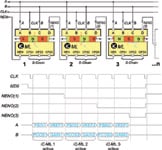 Figure 3. Daisy chain cascading of three linear measurement systems |
No further components are required for cascading. If the system has to log both rotational and linear motion, the iC-ML can be cascaded with an iC-MA (for rotational position sensing) to produce a mixed system.
The iC-ML in Operation
Figure 4 is a temporal diagram of the signals generated when an iC-ML in analog mode has been activated by the microcontroller. While the signals are being output to bus lines A and B, the microcomputer logs them at the two separate analog inputs. In the configuration selected these are the PSIN and PCOS signals in the first clock cycle, with the corresponding Vref and GAIN signals being output for evaluation of the magnetic field strength during the second clock cycle.
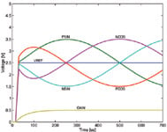 Figure 4. Analog output signals for the iC-ML following activation |
Following activation, the data in each clock cycle are stable after typically 150 µs, representing the correspond-ing electrical image of the magnetic position sensing. The patterns in Figure 4 are the periodic analog signal at a traversing rate of 5.12 m/s, using magnetic tape with a magnetic period of 5.12 mm or a 2.56 mm magnetic polar distance.
Depending on the operational configurations chosen from the analog signals depicted in Figure 4, either PSIN, NSIN, PCOS and NCOS, or PSIN, NSIN, Vref, and GAIN are permanent at four output pins (single device, as in Figure 2). Alternatively, two bus lines are available, distributed across two clock cycles (daisy chain array, as in Figure 3).
Applications
The system configurations involving a microcontroller as shown in Figure 2 and, in extended form, in Figure 3, are used in simple sensor systems to measure linear amplitudes, whether the amplitudes are linear expansion, vibration/oscillation, liquid levels, torsion, reciprocation, or position data. The noncontact, wear-resistant signal conditioning unit makes applications based on these sensor systems ideally suited to hostile environments or those subject to extreme fluctuations in temperature. Through its innovative use of Hall sensors and digital signal conditioning, the iC-ML is opening up a new field of application for linear measuring systems.
Reference
1. Quasdorf, Joachim, "A Case Study: MR vs. Hall Effect for Position Sensing," Sensors, Nov. 2005, pp. 15–20.
David Lin, Dr.-Ing., can be reached at iC-Haus, Bodenheim, Germany; +49-6135-9292-300, [email protected], www.ichaus.de.