

 The first four parts of this article, appearing in the May, June, July, and August issues of Sensors, addressed characteristics, materials, and configurations of the NTC thermistor; means of determining the level of uncertainty; the temperature-controlled bath; and the temperature calibration standard. The photo, figure, and reference numbers in Part V are continuous from the preceding articles.
The final (and probably the easiest) piece of equipment to evaluate is the resistance measuring instrument (see sidebar "Meas-uring Electrical Resistance"). Both analog and digital instruments are available, although there are fewer analog resistance bridges to choose from and they tend to be more costly than digital multimeters (DMMs) with equivalent uncertainty specifications. During the past few years, advances in DMM technology have greatly improved the performance of these instruments, making them a more cost-effective solution for testing thermistors. In addition, many DMMs come with standard communications ports that allow their use with an automated test system (see Photo 6). The specifications outlined below are usually listed in the manufacturer's literature, and more detailed explanations of the terms are given in [16].
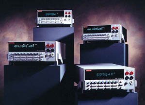 | Photo 6. Digital multimeters from Keithley offer a wide range of features including 4½ to 8½ digit resolution, built-in frequency counter, temperature measurement, 10-channel scanner capabilities, and Trigger-Lock technology for fast, precise triggering of multiple instruments. (Photo courtesy of Keithley Instruments.) |
A DMM's resolution depends on the number of digits that can be displayed; the user's test uncertainty (accuracy) and sensitivity requirements, along with budget constraints, will be the deciding factors in selecting the appropriate level of resolution needed. For some applications, a 4½ digit DMM, at a price of about $400, may be adequate. A testing capability with lower uncertainty requirements may require a 5½ or a 6½ digit DMM, costing about $600 or $1000, respectively. In general, the higher resolution DMMs have better uncertainty specifications.
Other areas to consider are the sensitivity and the test current. Because the DMM's resistance function is used to test thermistors, the sensitivity of the instrument is the smallest change in resistance it can detect. Sensitivity depends on the resolution and the lowest measurement range available on the DMM. For most thermistor applications, a 5½ digit DMM is sufficient and provides the overall best, most cost-effective solution. However, resolution and sensitivity must be evaluated with consideration of the test current the DMM applies at each appropriate resistance range anticipated.
A thermistor can experience self-heating if the test current and the resultant power dissipated through the thermistor are too high, so it is important to limit the test current level. When a thermistor self-heats, the resistance reading becomes less than that of its true zero-power resistance. For some thermistors, self-heating by the DMM test current can cause resistance deviations of 2–5![]() less than the zero-power readings, depending on the type of thermistor. Expressed in terms of temperature, these deviations increase the thermistor resistance measurement uncertainties by 0.03ºC– 0.06ºC, respectively.
less than the zero-power readings, depending on the type of thermistor. Expressed in terms of temperature, these deviations increase the thermistor resistance measurement uncertainties by 0.03ºC– 0.06ºC, respectively.
The amount of power a thermistor can dissipate depends on a number of factors, including size, shape, resistance value, configuration, coating material, and test medium. In general, the larger the thermistor and the higher its resistance value, the more power it can dissipate. Note, too, that a thermistor can dissipate more power into a stirred fluid than into still air. A typical epoxy- or phenolic-coated thermistor with a 0.095 in. o.d. and 0.010 in. dia. leads exhibits dissipation constants of 1 mW/ºC in still air and 8 mW/ºC in stirred oil. If the user's test requirement specifies that the uncertainty in measurement due to self-heat should be ![]() 0.01ºC, the maximum amount of power the thermistor should dissipate is [(0.01ºC)(1mW/ºC)] or 10 µW in still air and 80 µW in stirred oil. These power levels correlate to test currents of ~10 µA to 100 µA, depending on the resistance value of the thermistor. When choosing a DMM for testing thermistors, carefully review its specifications to be certain that the test currents for the applicable resistance ranges do not exceed these amounts. Usually, the DMM with the lowest test current, ~10 µA, is the best choice for testing thermistors.
0.01ºC, the maximum amount of power the thermistor should dissipate is [(0.01ºC)(1mW/ºC)] or 10 µW in still air and 80 µW in stirred oil. These power levels correlate to test currents of ~10 µA to 100 µA, depending on the resistance value of the thermistor. When choosing a DMM for testing thermistors, carefully review its specifications to be certain that the test currents for the applicable resistance ranges do not exceed these amounts. Usually, the DMM with the lowest test current, ~10 µA, is the best choice for testing thermistors.
One of the most important specifications to analyze when evaluating a DMM's capability is the manufacturer's stated uncertainty (or accuracy) of its resistance-measuring function. The uncertainty can be stated as a plus or minus percentage of reading plus a number of counts of the least significant digit, or in terms of parts per million such as ±(ppm of reading + ppm of range). The manufacturer usually states these specifications for periods ranging from 24 hours to one year. The one-year uncertainty specifications are particularly important because they give an indication of how well the instrument will stay within calibration over time. The measurement uncertainty expressed in terms of percentage of resistance or ppm of reading can be converted to temperature uncertainty by using the thermistor's NTC for each temperature at which the resistance readings will be taken.
If the test system's long-term uncertainty is especially crucial, consider purchasing stable resistance standards with values close to those of the thermistors to be tested and the temperature standard to be used for calibrating the bath. These standards can cost $200–$1000 each, depending on the uncertainty specified. Resistance standards can be very helpful tools for verifying the uncertainties of the resistance measuring instruments between calibrations.
Typical Methods for Testing Thermistors
When the appropriate test equipment is in place and in proper working order, it's time to make some final preparations. By carefully designing the right test clips and fixtures for the type of thermistors to be tested, for example, you will maximize the efficiency of the process and the repeatability of the results. Forms for recording data should be planned in advance and ready for use. This practice will help ensure that the test information will be recorded in an orderly and accurate manner, facilitating data analysis after testing is complete. The generic test sequence below can be modified for your specific requirements.
1. Temperature-controlled bath setup. The bath is set to the desired temperature, allowed to stabilize, and then calibrated. The time to complete these steps can be ~1/2 hour to 2 hours, depending on the bath temperature and its heating/cooling rates.
2. Resistance measuring instrument setup. The test clips or fixtures are connected to the DMM. The instrument is set to the resistance range with the proper test current and resolution for the thermistors to be tested. Many 5½ digit and 6½ digit DMMs have 20 k![]() and 200 k
and 200 k![]() ranges with 10 µA test currents, which cover most thermistor testing requirements.
ranges with 10 µA test currents, which cover most thermistor testing requirements.
3. Testing thermistors and thermistor probes. The thermistor leads are connected to the test clip and the thermistor is immersed in the bath fluid to a depth dictated by the type of thermistor being tested. A thermistor with bare leads is typically immersed 2–3 in. into the bath fluid, depending on the lead length and the test clip design. The proper immersion depth can be determined by trial and error until the best results are obtained. While testing, be careful not to immerse the test clip in the fluid because the added mass may disturb the bath's equilibrium temperature. The thermistor should be allowed to come into equilibrium with the bath temperature (typically 5–15 s). The test technician either records the resistance reading onto the data sheet or compares the reading to a predetermined acceptable resistance range if the reading need not be recorded.
When testing thermistors assembled into probe housings, the proper immersion depth becomes more critical for preventing resistance measurement errors due to a condition called stem effect, which is caused by heat transfer into or out of the probe. Such "thermal pipelines" create temperature gradients that distort the thermistor reading and must be compensated by using greater immersion depths. As a general rule, a starting point for immersion depth should be ~10 to 20 × the diameter of the probe. Taking readings at various immersion depths should reveal the optimum depth for testing. Also, a thermistor probe with its greater mass will require more time (typically 1–2 min.) to attain equilibrium with the bath temperature than will a small thermistor with bare leads.
4. Reviewing the data. Another simple but commonly overlooked step is to review the data while testing to see if the information seems reasonable. Making corrections or adjustments to the equipment before proceeding with the testing is much less time- consuming than having to completely repeat the testing sequence.
5. Other testing considerations. In Part I of this article, the drift characteristic of a thermistor was discussed. If the application requires an analysis of drift, extra care must be taken throughout the testing process to ensure that the resistance measurements have the best repeatability and lowest uncertainty possible. This extra effort will prevent the introduction of unwanted variables or errors that would distort the actual drift characteristic of the thermistor.
Conclusion
Technical advances have established the NTC thermistor as the optimum sensor for most applications within the –50ºC to 150ºC temperature range. The historical, theoretical, and practical information in this series of articles was intended to improve the reader's understanding of how to determine the appropriate temperature sensor for an application. The discussion of thermistor configurations highlighted the strengths and limitations of the three most common types used for resistance thermometry: glass bead, disc, and chip thermistors. Recommen- dations as to the setup and use of a thermistor test system should help the user evaluate thermistors for compliance with resis-tance/temperature specifications. As thermistor users and manufacturers strive to achieve a better working relationship, the result will be continued improvements in product design, quality, and service that ultimately will benefit the entire temperature measurement and control industry.
| Reference: 16. Low Level Measurements Handbook, 4th Ed. 1993. Keithley Instruments, Inc., Cleveland, OH:1-9.
|
Measuring Electrical ResistanceDale Cigoy, Keithley Instruments, Inc.Electrical resistance can be measured by either of two methods: constant voltage or constant current. The constant voltage technique sources a known voltage across an unknown resistance and measures the resulting current. This approach is used for ultra high resistance, in the 108 Digital multimeters (DMMs) are based on the constant current technique and typically have a range of 0.001 There are two versions of the constant current technique: the 2-wire method and the 4-wire method. The 2-wire is used for all general-purpose resistance measurements; the 4-wire is normally used for low-resistance applications.  Two-Wire Method. The 2-wire method sources and senses on the same two leads (see Figure 6). This means that a current is forced through the wires and the voltage is sensed with the same wires. Note that the voltage is sensed at the meter terminals and not at the resistive device. The technique is convenient and simple to use. For most resistance measurements, simply connect the two wires to the circuit of interest and read the DMM display. Four-Wire Method. The 4-wire method sources current with two wires and senses the voltage drop on another set of two wires (see Figure 7). This allows the voltage to be detected at the resistance under test. The 4-wire technique has the advantage of eliminating test lead resistance as it measures the resistive device. Test lead resistance is generally several hundred milliohms in magnitude, and represents a large offset in a low-resistance measurement. To eliminate test lead resistance, most DMMs offer a feature designated Zero, Null, or Relative. Using it is a two-step procedure. First, short the two test leads together. Next, enable the Zero feature. This step subtracts the measured short-circuit resistance from every subsequent reading. Dale Cigoy is Senior Applications Engineer, Keithley Instruments, Inc., 28775 Aurora Rd., Cleveland, OH 44139-1891; 216-248-0400, fax 216-248-6168. |
The Three-in-One DP100Jay Long, Analogic Corp.
A resistance accuracy of ±0.007% permits the confident sorting and testing of precision networks. The 200,000 count resolution allows pinpoint detection of very small changes in large values. A digital filter averages noisy signals for more stable readings. The instrument measures temperature by means of RTDs, with a specified accuracy of ±0.3ºC (plus probe errors) from –200ºC to 250ºC (–328ºF to 482ºF). The 4-wire connection permits long cable runs without compromising the inherent measurement accuracy. Temperature is displayed directly in degrees Celsius or Fahrenheit. Under RS-232 control, it can be used to make precise temperature coefficient measurements. Other features include simple, intuitive operation based on five control keys; password protected, closed-case calibration; and the ability to interface with nearly any serial printer or computer via a built-in, optically isolated RS-232 interface. Compact, rugged, and weighing 3.5 lb. (1.6 kg), the DP100 can be conveniently transported from site to site. Jay Long is Sales Manager, MCD Div., Analogic Corp., 8 Centennial Dr., Peabody, MA 01960; 508-977-3000, fax 508-977-6814, [email protected] or http://www.analogic.com |
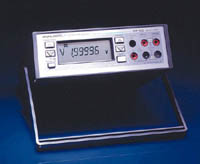 The DP100 digital multimeter serves as three instruments in one, measuring temperature and providing high-frequency measurements and true rms AC. The accuracy and sensitivity of this 5½ digit instrument satisfy the requirements of most development engineers, critical field service groups, and production personnel.