

Process industry engineers who use fieldbus in their hazardous location applications (Class I, Division 1 and Class I, Division 2) are looking for additional power that will let them connect more instruments to their fieldbus segments. Three emerging methods promise to help meet this need: FISCO (Fieldbus Intrinsically Safe COncept), FNICO (Fieldbus NonIncendive COncept) and the High Power Trunk concept.
Entity, FISCO and FNICO
When fieldbus technology was first introduced, the entity concept with cabinet-mounted barriers and power supplies was standard for hazardous areas. But it supplied enough power for only three or four instruments per segment, and matching entity parameters of devices and power source was quite cumbersome. Because the entity model was based on the cable's concentrated inductance and capacitance, less electrical power could be transmitted into the hazardous area than became possible with subsequent models. Furthermore, for each configuration or addition of a fieldbus device, intrinsic safety usually had to be rechecked.
The FISCO model was therefore developed for Class I, Division 1 applications to verify intrinsic safety without requiring a parameter evaluation. FNICO was created for Class I, Division 2 applications to simplify the certification of a nonincendive fieldbus segment. The two models have certain features in common:
- 1. The fieldbus is based on the physical layer per IEC 61158-2 (ISA S50.02).
- 2. There is only one active source (power supply with trapezoidal output characteristic), which is certified in accordance with FISCO/FNICO per system. All other devices act as passive current sinks.
- 3. The basic current consumption of a device is ≥10 mA.
All devices must meet the following requirements:
Ui / Vmax ≥o / Voc of power source
Ii / Imax ≥ / Isc of power source
Pi / Pmax ≥o of power source (FISCO only)
Nodes have negligible internal inductance and capacitance:
Ci ≤5 nF, Li ≤10 μH
- 1. Maximum cable length is 1000 m
- 2. Maximum spur length is 60 m
- 3. The fieldbus cable must have the following characteristics:
15 Ω/km < R' <150 Ω/km
24.1 Ω/mi. <R' <241 Ω /mi.
0.4 mH/km ≤L' ≤1 mH/km
0.64 mH/mi. ≤L' ≤1.61 mH/mi.
80 nF/km ≤C' ≤200 nF/km
129 nF/mi. ≤C' ≤322 nF/mi.
- 1. The bus segment must be terminated on both ends.
- 2. The type of devices to be connected to a FISCO- or FNICO-approved barrier are shown in Figure 1.
Note that most FISCO devices can also be used with the entity concept, but neither FISCO nor FNICO models consider the cable capacitance and inductance to be concentrated, as in the entity model. More devices can therefore be connected to the bus in a FISCO or a FNICO system than in an entity system.
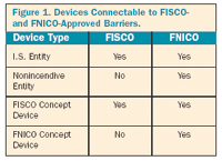 Figure 1. Devices Connectable to FISCO- and FNICO-Approved Barriers. |
Not a Complete Solution
Although FISCO/FNICO models offer more power than entity, they do not deliver the benefits of fieldbus in a general-purpose configuration. In practice, limits on cable and spur length and very low current and voltage levels mean significantly shorter cable runs than the theoretical maximums. Additionally, neither FISCO nor FNICO power conditioners provide online physical layer diagnostics or redundancy.
End users also wind up with more hardware in their control-room cabinets, and they must install yet more hardware in a centralized control room. These inconveniences go against the grain of a distributed fieldbus architecture.
The High Power Trunk Concept
The High Power Trunk concept (HPT) is a new way to handle both hazardous area applications and satisfy general-purpose fieldbus requirements. HPT (see Figure 2) does not limit the energy on the fieldbus trunk cable to intrinsically safe or nonincendive levels. Rather, it limits the energy on the spur connections that reaches the instruments. Users can therefore install the maximum number of devices on a segment and not be limited by cable length.
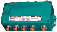 Figure 2. Fieldbus segment protectors connect nonincendive and general-purpose fieldbus devices to a fieldbus trunk, and provide short-circuit and overload protection for up to 12 spurs. This unit from Pepperl+Fuchs mounts inside safe locations or in Class I, Division 2 or Zone 2 hazardous areas. |
Recently introduced technologies such as fieldbus barriers and fieldbus segment protectors make it both possible and easy to apply the HPT method in practice. Both are typically mounted in a Division 2 area where HPT connections are made. Note that when using the High Power Trunk method, the trunk has to be wired according to Division 2 wiring methods.
Depending on the application, protection (energy limitation) is performed in the field and not on the trunk, allowing HPT users to enjoy the same benefits in terms of power, cable length, and number of devices per segment in hazardous location applications as they do in general-purpose applications.
HPT works for all fieldbus applications (see Figure 3). It simplifies segment design, minimizes the amount of hardware, supports a distributed architecture, permits live maintenance, and offers state-of-the-art power redundancy and online physical layer diagnostics. To summarize its other advantages:
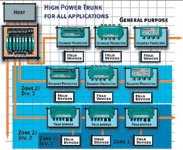 Figure 3. The High Power Trunk concept is designed for all fieldbus applications. |
- 1. Same topology regardless of application
- 2. Up to 32 devices per segment
- 3. Maximum cable length
- 4. High, reliable fieldbus power
- 5. Online, physical layer diagnostics
- 6. Works with all instruments (entity, FISCO, FNICO, Div. 2, Zone 2, Standard) n