
Performance improvements and reductions in the size and cost of MEMS pressure sensors in recent years have also enabled this component to be combined with inertial and magnetic sensors for dead reckoning and navigation applications in consumer products.
In this article we introduce atmospheric pressure vs. altitude, describe altitude calculations by using the pressure sensor, and discuss how to integrate the pressure sensor into a pedestrian navigation device such as a smart phone.
Atmospheric Pressure vs. Altitude
In a pedestrian navigation application, a MEMS pressure sensor can be used as a barometer to measure the altitude change. Because we live at the bottom of the earth's atmosphere, as altitude increases, the air pressure decreases. The standard atmosphere (1 atm) is defined as 29.92 in.Hg at sea level at a temperature of 59°F. This averaged number will change very little over time, although there is some variation based on the location on earth and the temperature and air density at those locations.
Atmospheric pressure can be described using any of the following units:
- pounds per square inch (psi)
- centimeters of mercury (cm.Hg)
- inches of mercury (in.Hg)
- Pascal (Pa), the SI unit for pressure and equal to 1 N/m2
- bar, an air pressure unit equal to 105 Pa
- millibar (mbar) equal to 10–3 bar
The relationship between the units is:
1 atm = 14.7 psi = 76 cm.Hg = 29.92 in.Hg = 1.01325 bar = 1013.25 mbar
The atmospheric pressure vs. altitude can be expressed as Equation 1 [1]:
| (1) |
where:
| P | = | the air pressure at the altitude in the unit of mbar |
| P0 | = | the standard atmosphere, 1013.25 mbar |
| Altitude | = | the height above sea level in meters |
Based on the formula, we can see that the air pressure changes with altitude as shown in Figure 1. As the altitude increases from sea level to 11,000 m, the air pressure decreases from 1013.25 mbar to 230 mbar. The graph also shows that when the altitude is <1500 m, the air pressure decreases almost linearly at a rate of about 11.2 mbar per 100 m, or 1.1 mbar per 10 m. For more accurate altitude measurement, a look-up table can be constructed to retrieve the altitude based on the air pressure as measured by the pressure sensor. For an absolute MEMS pressure sensor with a F.S. measurement range of 300–1100 mbar, we can measure the altitude from 9165 m above sea level to 698 m below sea level.
 Figure 1. Air pressure vs. altitude |
Floor Detection Using a MEMS Pressure Sensor
A MEMS pressure sensor with 0.1 mbar rms resolution can detect an altitude difference of <1 m and can therefore be used to distinguish between floors inside a multistory building.
Figure 2 shows the raw pressure sensor data collected in the STMicroelectronics office building in Castelletto, Italy. The sampling rate is 7 Hz and the total data acquisition time is about 23 min. We can see that the air pressure changes at the different floors. In the basement, the air pressure is highest. As we ascend through the building, the air pressure gets lower and lower.
x x xFigure 2. Floor detection from ST pressure sensor raw data |
Note that pressure sensor measurements can be affected by wind flows and weather conditions. For accurate and reliable floor detection we need to develop an appropriate sensor calibration and filtering algorithm.
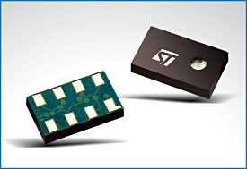 Figure 3. ST MEMS pressure sensor |
A MEMS Pressure Sensor in Pedestrian Navigation
Most current smart phones have a built-in global positioning system (GPS) receiver and low-cost MEMS motion sensors such as an accelerometer or a gyroscope, and/or a magnetometer. Pedestrian navigation or dead reckoning becomes important when the GPS signal is not available, which can occur inside a building or in an unserved urban area. Because altitude measurements from the GPS receiver are inaccurate, both indoors and outdoors, a MEMS pressure sensor can be integrated into the smart phone to aid the GPS altitude measurement.
The pedestrian navigation system (PNS) is similar to the pedestrian dead reckoning (PDR) system. Basically, the concept is that whenever the GPS signal is not available, the PNS or PDR can continuously provide position and heading information on a digital map on a smart phone to guide users to some point of interest for location-based services (LBS).
The heading information can come from a magnetometer, gyroscope, or both. The positioning information can come from either double integration of accelerometer measurements based on an inertial navigation system (INS) scheme for PNS or from a step-counter and step-length estimator from a typical pedometer application, again using the accelerometer, for PDR. After the heading and distance traveled are obtained over time, the pedestrian's indoor location can be updated on the digital map displayed on the smart phone.
PNS or PDR block diagram. The PNS or PDR block diagram is shown in Figure 4. In terms of MEMS sensors, it contains a 3-axis accelerometer, a 3-axis gyroscope, a 3-axis magnetometer, and a pressure sensor. In addition, the block diagram includes a GPS receiver and a host microprocessor that acquires the sensors' data and runs the dead reckoning and Kalman filtering algorithm.
 Figure 4. Personal navigation system (PNS) or pedestrian dead reckoning (PDR) block diagram |
The pros and cons of each component in Figure 4 are described below:
Pros | Cons | |
GPS Receiver |
|
|
Accelerometer |
|
|
Gyroscope |
|
|
Magnetometer |
|
|
Pressure sensor |
|
|
PNS or PDR implementations. There are two schemes to implement PNS or PDR in a smart phone. The first one is based on a strap-down inertial navigation scheme (SINS) for PNS and the second one is based on a pedometer for PDR. Both have advantages and disadvantages.
SINS is based on a 3-axis accelerometer and a 3-axis gyroscope that form a 6-degrees-of-freedom (DOF) inertial measurement unit (IMU). The scheme has been well developed and implemented in rigid bodies such as vehicles and missiles where the IMU is permanently mounted. It can provide relatively high position accuracy in a short time. Due to the bias drift of low-cost MEMS motion sensors, the position error will grow over time after integration and double integration whenever the GPS signal is not available. In addition, pedestrians usually put their smart phones in their pockets or on their belts. They will check their positions randomly by taking their smart phones out from their pockets. In other words, the smart phones do not have a fixed location with respect to the pedestrian's body. However, SINS/GPS integration for PNS is user-independent, which means that any user can use the smart phone without modeling and training for different kinds of pedestrian motions such as walking, running, and stepping up or down stairs.
The advantage of the pedometer/GPS integration for PDR is that the position accuracy relies mainly on estimations of the number of steps (counted by the accelerometer) and the length of the steps (calculated by the pedometer algorithm, which can be calibrated by the GPS). Therefore the positioning error is always limited [2].
The first step for PDR is to use the accelerometer to accurately detect footsteps [3]. The idea behind this is to automatically find the dominant vertical axis, no matter how the smart phone is placed on the pedestrian's belt or hip. Then, the acceleration measurements are compared with the first reference threshold so that, subsequently, the reference threshold will be updated adaptively based on different kinds of motion. This allows accurate counting of pedestrian footsteps when the pedestrian is walking, running, or climbing stairs.
The second step is to calibrate the step length when the GPS antenna has a clear view to the sky. To do this, the pedestrian's smart phone can obtain the averaged step length by dividing the distance traveled (based on GPS measurements) by the number of steps taken (counted using the pedometer algorithm). This requires calibration procedures for all possible pedestrian motion scenarios such as slow walking, fast walking, slow running, fast running, going up stairs, and going down stairs; different pedestrians have different motion styles. Therefore, PDR is user-dependent and an auto-calibration or self-training algorithm for step-length estimation is required for all pedestrians.
The third step is to obtain accurate heading information from the combination of the accelerometer, gyroscope, magnetometer, and the GPS receiver data. After step length is estimated, we also need the absolute heading with respect to geographic north. A tilt-compensated digital compass generated from the accelerometer and magnetometer can give an accurate heading in a clean environment with respect to earth's magnetic north.
Taking a GPS fix before entering the building can allow the smart phone to retrieve the declination angle based on the current location. Then, the heading from the compass can be converted into a geographic heading. The magnitude of the magnetometer measurements can also be used to extract the information whether a surrounding magnetic interference field is detected or not. If magnetic interference is detected, the gyroscope will take over to provide a continuous heading output based on the last clean compass heading output. Once the external magnetic interference is no longer present, the gyroscope will be stopped to reduce the system's power consumption and the compass will start to work again. This is called a gyroscope-aided digital compass. When the accelerometer shows the smart phone is at rest, it can let the gyroscope update the zero rate level for future use.
The fourth step is to get accurate altitude information from the pressure sensor and GPS receiver. When the pedestrian is taking the stairs or an elevator in a shopping mall, for example, the pressure sensor can update the digital map to show the current floor.
The fifth step is to develop the Kalman filtering algorithm to fuse the ten-dimensional sensor module data with the GPS data. All GPS receivers have a 1 pulse/s (PPS) output signal to synchronize the GPS with the sensors while the sensors can be sampled at a faster rate, e.g., 50 Hz or 100 Hz. The Kalman filter will use the GPS outputs for navigation when a GPS signal is available and use dead reckoning when a GPS signal is blocked. It can also estimate the sensor errors for compensation when the GPS signal becomes available again.
The last step is to test the performance of the PDR in the smart phone. Usually for consumer electronics it is acceptable to have a 5% error in the distance traveled. For example, when the pedestrian walks indoors for 100 m, the error should be within 5 m.
Conclusion
Advances in MEMS technology and processes has led to low-cost, high-performance MEMS accelerometers, gyroscopes, magnetometers, and pressure sensors that feature lower power consumption and smaller sizes and that enable the development of exciting applications for handheld devices such as smart phones.
The MEMS pressure sensor is becoming very attractive for navigation for outdoor unmanned aerial vehicles (UAV) and indoor PDR. With further development of advanced algorithms, we believe that we can achieve a 5% indoor PDR error on distance traveled.
References
1. U.S. Standard Atmosphere, 1976 (PDF)
2. Honeywell International Inc., "Dead Reckoning for Consumer Electronics"(PDF)
3. STMicroelectronics, Inc., Fabio Pasolini et al., "Pedometer device and step detection method using an algorithm for self-adaptive computation of acceleration thresholds." United States Patent 7463997.
About the Authors
Jay Esfandyari, PhD, is MEMS Product Marketing Manager for STMicroelectronics Inc., Coppell, TX. He can be reached at 972-971-4969, [email protected].
Massimo Mascotto is Senior Marketing Engineer at STMicroelectronics and can be reached at +39 346-629-7263, [email protected].
Gang Xu is Senior Application Engineer at STMicroelectronics and can be reached at 408-467-8402, [email protected].