

Inductive proximity sensors are inexpensive, durable, and resistant to industrial contaminants. But if your sensor will be exposed to target impacts, abrasion, corrosive cutting compounds, and other abuse, you need to pay very close attention to which sensor you choose and how you mount it.
 |
Mounting. A case in point is Die-Matic Corp. in Brooklyn Heights, OH, a manufacturer of specialized tools and progressive dies and producer of precise metal stampings. With nearly 250 dies equipped with up to 40 sensors per tool, sensor failure is not an option. According to Die-Matic's sensor application specialist Steve Kerg, unplanned shutdowns can cost the company as much as $2000 an hour. The operating environment is severe. Many of the sensors are submerged in a cutting compound with a high chlorine content that makes PUR sensor cables brittle and easily cracked. A switch to PVC solved that problem.
 Lack of proper protection in a welding operation can turn your shiny new inductive prox sensor into the sorry example. |
Installing the sensors on the dies is a more challenging chore, though. Kerg estimates it takes upwards of eight hours per sensor to ensconce it in a protective die block (see Figure 1) and install the unit in its proper place. That might seem like a long time to spend on a single sensor, but, coupled with regularly scheduled maintenance, the practice has paid off by making sensor-related downtime nonexistent.
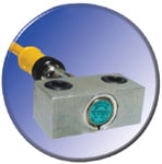 Figure 1. Taking the time to properly install sensors will, in the long term, save significant downtime and maintenance headaches. These proximity sensors are mounted in custom-made die blocks to protect them from harsh application elements. |
You can also extend sensor life with cushioned mounting brackets (see Figure 2) incorporating an integral spring-loaded mechanism that protects against target overtravel. When the sensor gets hit by the target, the spring compresses and absorbs the impact; when the target retracts, the spring extends back to its original shape. Or you can outfit your sensor with inexpensive Teflon or Delrin caps that simply thread over the sensing face to protect it from abrasion.
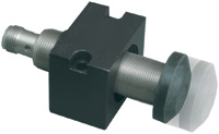 Figure 2. Cushioned mounting brackets are a popular means of protecting sensors against target impacts. |
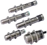
Extended Range. Sensors are usually placed not at the maximum distance from a target but rather at 40%–80% of that distance to allow for various manufacturer and application tolerances. Standard cylindrical inductive sensing distances range from 0.8 to 15 mm, proportional to the diameter, so the actual sensor-target separation is typically <12 mm. As manufacturing equipment becomes more compact, the space available for special mounting brackets and assemblies shrinks. You might want to consider using "extended range" sensors (see Figure 3) to mitigate damage. .
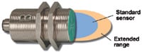 Figure 3. Extended-range sensors offer 25%–200% more sensing range than conventional inductive sensors. The greater range allows them to be mounted farther from the target. |
Increased sensing distance reduces target-sensor collisions by allowing the sensor to be mounted at a greater—and thus safer—distance from the objects they detect. Some of these extended-range sensors have as much as double the range of regular inductive proxes, and are available in virtually all industry-standard housing types
Metal Faces
Some manufacturers have used special oscillator/coil arrangements to make inductive sensors with stainless steel sensing faces that "see through" the face metal and detect the opposing target metal. This type of sensor is particularly handy in the metal-forming industries where metal-on-plastic abrasion can quickly add conventional sensors to the scrap pile.
Metal face products are available in a variety of industry-standard housings, with AC or DC outputs. Their cost is also very competitive with conventional models. It is important to note, though, that not all metal-faced sensors are created equal. Some manufacturers use thin foils rather than machined barrels, and the resulting sensors are scarcely more durable than their plastic-faced cousins. When your sensor will have to endure abrasion and impact, be certain its face is at least 0.4 mm thick.
How much longer does a metal face sensor last? Abrasion testing (see Figure 4) at Pepperl+Fuchs determined that a 0.4 mm thick stainless steel sensing face produced a sensor life span more than 20 x that of an equivalent plastic-faced model.
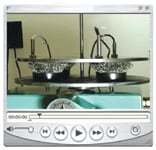 Figure 4. Pepperl+Fuchs conducted an abrasion test comparing metal-faced, nickel-plated brass, and stainless steel inductive sensors. Metal-faced sensors tested to last 20 x longer than conventional inductive sensor options. View the dramatic results online at www.am.pepperl-fuchs.com/ pdmovie/. |
Welding Environments
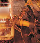
Automated welding operations often rely on proximity sensors to accurately position the metal parts. But bonding two pieces of metal with an electrical weld requires a tremendous amount of energy. The high currents used in resistance welding can produce a magnetic field strong enough to false-trip standard proximity sensors—the magnetic field saturates the coil system and the sensor mistakenly thinks it sees a target. Your prox sensor can also be confounded by the slag (see Figure 5), also called flash or spatter, that is a byproduct of resistance welding.
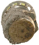 Figure 5. The release of energy during the welding process causes a dispersion of small, hot metal fragments referred to as weld slag, flash, or spatter. Conventional plastic-faced sensors are prone to slag accumulation that will significantly reduce sensor accuracy and life. |
The good news is that there are weld-immune sensors (see Figure 6) specifically designed for reliable operation in the presence of strong magnetic fields and capable of repelling weld spatter. How do sensors "ignore" weld fields? One way is through the use of special core materials such as carbonyl iron, which has 2–3 x the saturation flux density of the conventional ferrite. "Coreless" sensors are also immune to weld fields, but they often require target sizes that are larger than normal, and without a core for internal structural support, they are highly susceptible to side impact damage.
As for spatter damage, manufacturers can coat standard housings with a variety of slag-repellant materials and apply ceramic "paints" to the sensing barrels and faces. Teflon, epoxy-based paint, or other coatings are sometimes baked-in to the sensor housings and plastic caps to prevent molten beads of slag from accumulating during welding. The spatter simply slides off, and plant maintenance personnel don't need to knock it off with a hammer or other percussive removal tool.
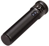 Figure 6. Automated welding processes often rely on proximity sensors for accurate positioning of metal parts. The combined presence of hot weld slag and strong electromagnetic fields can create an environment unsuitable for standard proximity sensors. Pepperl+Fuchs’s weld-immune proximity sensors are specifically designed for reliable operation in such conditions. |
Washdowns, Temperature, and Other Concerns
If your sensor is likely to experience high-pressure wash downs, steam, or other heavy-duty cleaning operations, make sure it is sealed against liquid ingress. If the high shock and vibration common in mobile equipment and rail applications are likely, make sure your sensor has the encapsulates it needs to protect its internal electronics and coil system. Are aggressive chemicals present? Choose housing and cabling that will withstand them. For severely fluctuating ambient temperatures, make sure that the sensor you select has encapsulates that will protect its electronics from the effects of expansion and contraction. See what's out there by visiting sensor manufacturers' application engineering groups or Web sites.
 Inductive Proximity Sensor Basics |
Summary
General-purpose sensors are just that—out-of-the-box and suitable for 80% of applications. The time-tested "80/20 Rule" guarantees that the remaining 20% will consume most of your time. Choosing the right prox sensor and carefully thinking out its mounting can dramatically reduce the headaches and expense of unplanned downtime. In short, know the ropes and move forward with confidence.
You can find a potential cost-savings calculator at www.am.pepperl-fuchs.com/PDC/. A short video illustrating the abrasion testing referred to in Figure 4 is at www.am.pepperl-fuchs.com/pdmovie/ .
Joan Kassan is a Technical Writer and Marcel Ulrich is Product Manager—Inductive Sensors, Pepperl+Fuchs, Twinsburg, OH; 330-486-0001, [email protected], mulrich@ us.pepperl-fuchs.com, [email protected], www.am.pepperl-fuchs.com