

A basic lack of consumer awareness of the limitations of GPS has acted as a barrier to true mass adoption of the technology. Continued improvements in receiver size, performance, and cost have fueled an explosion of consumer GPS products during the past several years, and public awareness of the potential utility of GPS has similarly increased. Telematics systems, locatable mobile phones, GPS-enabled PDAs, and more novel GPS products such as pet finders have flooded the marketplace, with new products and applications announced almost daily. Yet many consumers are dissatisfied by the low position accuracy their devices furnish under some circumstances — if indeed they can obtain a position at all.
Consumers expect a product simply to work, irrespective of the conditions to which they subject it. A GPS receiver should tell them where they are — whether they're inside a car or building or whether the receiver is buried inside a pocket or purse. The consumer shouldn't be asked to shoulder the burden of ensuring the receiver has a clear line of sight on a cloudless, sunny day, while holding the receiver at arm's length.
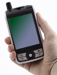
In fact, it is a sure sign of a nervous GPS device demonstrator when he or she holds the device between thumb and ring finger in the genteel manner in which one might hold a teacup! Such a delicate grip betrays an attempt to preserve antenna efficiency, reducing the effect of body loading by minimizing the mass of human tissues in close proximity to the device. Body loading constitutes a critical issue in the design of portable GPS products, because it accounts for much of the loss of receiver sensitivity and can lead to unacceptable performance even when a device is used in the manner intended by the designer.
 Antenna Terms |
The loss of electromagnetic resonance energy as it dissipates into the lossy body impairs receiver sensitivity. The antenna's function is to resonate an electromagnetic cloud in the space surrounding the antenna. The resonance of that electromagnetic near field actually causes radiation of energy to the far field, which is the field perceived as the doing the antenna's work. GPS receivers, of course, deal with the inverse of this process — energy from the far field causes a resonance in the near-field cloud surrounding the antenna. If a user presents his or her body into the space occupied by the near field, the energy that ordinarily would be available to the receiver dissipates into the user, and sensitivity decreases. With conventional antennas, the near-field region is large (as much as three wavelengths in radius or almost 2 feet for GPS), and the loss of receiver sensitivity to loading can reach as much as 10 dB. Therefore, designers must face the key challenge of antenna efficiency in a body-loaded environment.
Although many advances have been made in receiver design, increasing receiver sensitivity to very low levels with or without network assistance, the drive to make antennas smaller runs counter to the need to make them more efficient. After all, with antennas, bigger is better. Expressed simply,
(gain × bandwidth)/volume = constant
If the volume decreases, then (gain × bandwidth) also must decrease. Most device designers try to squeeze the maximum amount of gain from a small antenna by recognizing that a conventional antenna must resonate against a ground plane, which when coupled with the device effectively increases antenna volume to the volume of the device itself. Unfortunately, user interaction with the device in applications in which the device is to be held, worn, or sit in a user's pocket causes the antenna to de-tune and lose energy to the lossy materials surrounding it — a vicious circle.
Consumer applications require an antenna large enough to provide sufficient signal to the receiver, small enough to attractively fit small products, and isolated from the device so it doesn't interact with its environment — except to resonate with received GPS signals. Only then can we can consider products that will work when sitting in a user's pocket or purse. The dielectrically loaded quadrifilar helix antenna provides such a structure.
This topology takes control of the resonant near fields by using a high-dielectric core. A feed topology isolates the antenna from the handset ground. A balanced feed system attenuates conducted in-band, common-mode noise that would otherwise impair the sensitivity of the connected GPS receiver. This independence from its environment leads to electrical performance of the antenna that is predictable across all environments of normal use.
 Figure 1 Fields around a point dipole. |
Near and Far Fields
We can visualize antenna behavior in terms of the near/far field issues in the context of portable wireless devices using a mathematical analysis of the simple point-dipole antenna. Putting the argument in terms of radiating antennas makes this easiest; because antennas obey the law of reciprocity, the same conclusions arise with receiving antennas. We can couch the analysis in a polar coordinate system so that the angle Φ denotes the angle concentric to the direction of the dipole, and the angle θ represents the angle around planes bisected by the direction of the dipole (see Figure 1). The antenna is small enough to permit the assumption that the angle from a point to one pole does not differ significantly from that point to the other pole; both paths have angle θ.
The magnetic fields surrounding the point dipole can be calculated from the curl of the magnetic vector potential (Â) of the point dipole.
 |
The electric fields surrounding the point dipole can be calculated from the curl of the magnetic field. From Equations 1 and 2 the field structure of the point dipole can be represented in terms of a polynomial in 1/jkr, where k is the wave number (k = v/c).
It is interesting to examine the physical basis of these terms. We see that, in line with the right-hand rule for a z-directed current, the magnetic field circulates concentrically around the dipole and therefore is oriented purely in the Φ direction.
The term in (1/jkr)2 is called the induction field or near field because it is the dominant constituent of magnetic field close to the antenna. The magnetic field term that is responsible for the radiation function of the antenna is that in 1/jkr, which dominates at distances far (kr>>1) from the antenna. This term is responsible for the time-average power flow from the source.
An examination of the electric field terms tells a similar story. The terms in (1/jkr)3 are electric-dipole field terms, often called the electrostatic solution because they are present at zero frequency. These terms together with the intermediate (1/jkr)2 terms are dominant near the dipole and are near-field terms. For antenna function the most important term once again is the 1/jkr field term in i θ which is a radiation field term and is the dominant constituent of the electric field at a distance that is far from the antenna.
The near-field terms do not contribute to power flow from the antenna. They can be visualized as stored energy in the magnetic and electric fields and therefore often are called the reactance fields. This phrase tells us that antennas are surrounded by rather dense electromagnetic fields associated with the resonance of the antenna close to the antenna. Further away from the antenna, a radiation field predominates.
The format of Equations 1 and 2 indicate that the near-field and far-field terms are, in the case of the simple-point dipole, related in a polynomial function. If the space occupied by the antenna is uniformly a medium of dielectric permittivity (є), then changing that permittivity will cause all near-field and far-field terms in Equation 2 to change to the same degree.
Intuition and empirical experiments do not support this interpretation for the case of multimedia antennas. Consider an electric-field dipole built across a high-dielectric core so that the electric field is mainly disposed between the charge poles in the dielectric medium, but the actual position of the poles is on the surface boundary between the dielectric and free-space media. Clearly, the electric fields in such a structure would be concentrated into the dielectric medium, both by the balanced nature of the dipole offering field across the dielectric medium and also because the energy density (ω) of an electric field is proportional to є:
 |
If, apart from the introduction of the dielectric media between the poles of a dipole, no other differences from the free-space dipole are introduced, then the modified forms of Equations 1 and 2 become very complex to reflect the existence of a slow-wave/fast-wave media boundary acting in the region of the near-field terms and the absence of such influences in the far-field region. These relationships depend upon the geometry of the antenna system, the dimensions and shape of the dielectric medium, and its position and orientation relative to the dipole. We can say from empirical experience or analysis of simple antennas that the dielectric loading reduces the volume in which movement of radio frequency (RF)–reflective objects close to that antenna causes reactive tuning of the antenna. We can also be fairly certain that, to first order, the gain of antennas dielectrically loaded with low-loss materials depends only on the enclosed volume of the antenna in the same continuum that encompasses conventional free-space antennas.
In practical application, the energy drained from the near-field region caused by the presence of dielectric materials entering that region represents energy lost from the GPS communications link. This loss can cause a significant impairment to the link performance of the communications system. Because human body tissues have an єr of approximately 40, a user's hand placed in that region, grasping the device on which the antenna is mounted, will reduce antenna efficiency. Therefore, containing the near field very close to the antenna so that no opportunity exists for a user (or other dielectric materials) to interact with it is important in yielding a very stable and predictable performance from an antenna. The dielectrically loaded quadrifilar helix antenna achieves this goal by design.
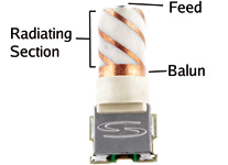 Figure 2 Structure of the dielectrically loaded quadrifilar helix |
Quadrifilar Helix Antenna
One example of such an antenna, shown in Figure 2, consists of copper tracks surrounding a 10 × 17.5 millimeter high-dielectric core. An integral balun in the structure ensures a balanced feed signal is projected to the top of the antenna. Just as importantly, the balun provides isolation for the currents on the antenna element from the handset. The antenna has two quadrature-phased bifilar-helical loops, and the phase quadrature is achieved by the two loops having slightly offset resonant frequencies. One of the bifilar helices is adjusted longer than resonance to produce an input impedance with a phase angle of +45 degrees, and the other bifilar is adjusted shorter than resonance to produce an input impedance with a phase angle of -45 degrees. This difference produces the 90-degree phase shift between the currents in the first bifilar with respect to the second bifilar, as required for quadrature.
When operating in the axial loop mode of resonance, the virtual electromagnetic dipoles formed by the two orthogonal bifilars are 90 degrees out of phase and they combine to give a virtual spinning dipole effect. The effective spinning dipole means the antenna is circularly polarized, yielding the characteristic cardioid right-hand circular far-field pattern.
At resonance, the current propagation in the loop mode sees the current pass down one helix around the balun rim, and back up the geometrically opposed helix to complete the 360-degree loop. At resonance, the currents should be equal in magnitude and opposite in phase approximately one-half of the way up the radiating section. The crowned rim induces phase differentials in the helical loops, which are required to complete the phase quadrature.
Figure 3 shows that no currents are present at the base of the balun, and that the balun has prevented currents from flowing between radio and antenna radiating section, isolating the antenna from noise sources.
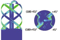 Figure 3 Current flow and phase quadrature in the axial-loop mode |
In measurement, the constrained near-field properties of this antenna are simply demonstrated by measuring the S11 parameter (an RF parameter called "return loss" — the amount of energy not reflected back down the feed cable when you insert a signal) of the antenna. As Figure 4 shows, the antenna exhibits a negligible frequency shift as a hand is moved closer to the antenna, still with acceptable return losses (voltage standing wave ratio [VSWR] of less than 1.5:1) even when the hand is 5 millimeters from the radiating surface of the antenna.
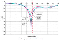 Figure 4 A S11 plot of the passive quadrifilar helix antenna in free space (blue), with hand 10 millimeters away from radiating section (red), and 5 millimeters away (green) |
Likewise, the radiation pattern of the antenna demonstrates its imperviousness to near-field loading factors. Figure 5 compares the radiation patterns of the antenna in free space versus hand-loaded space. Note that the demonstrated radiation pattern approaches the Euclidean ideal for cardioid, even when loaded. This has important implications for GPS receiver performance, in that most antenna gain is concentrated in the upper hemisphere, indicating strong bias for circular polarization, and the antenna has very broad beamwidth to provide much better reception of signals from satellites that are low on the horizon.
 Figure 5 Radiation pattern of quadrifilar helix antenna in free space and hand-loaded space |
Practical Design Considerations
An antenna with these properties has interesting implications for receiver designers. First, the antenna's stability near dielectric materials will make the task of integrating the unit into the housing much simpler. With conventional antennas, changes in radio materials and shape affect antenna tuning, in many cases enough to require alterations to the antenna's structure and resonating length. The frequency stability of the dielectrically loaded quadrifilar helix antenna around dielectric materials means that antenna component can be standardized at the beginning of the design cycle rather than the end.
A second important consideration is how the antenna reacts to conducted in-band noise from other components in the radio. Under the conventional single-end-fed antenna scenario, noise from electronics in the radio is conducted by the ground plane coupled with the antenna into the receiver. Although filtering can remove out-of-band noise from the signal, the receiver gets degraded carrier-to-noise levels from in-band sources. The choking effect of the antenna's integral sleeve balun ensures that no electrical coupling exists between the device's ground and the antenna; this conducted noise has no path in which it can enter the antenna-to-receiver chain.
Two interesting corollaries of this isolation property follow. First, the entire receiver device now can be made as small as the antenna. As Figure 5 infers, the total radiation efficiency of the antenna is approximately 23 percent, whether the antenna is in free or loaded space. Although this efficiency is approximately one-half of what can be obtained from a 25-millimeter microstrip patch antenna with a 40-millimeter ground plane, which has roughly three times the radiating area of the quadrifilar antenna, the patch antenna remains quite susceptible to the body-loading effects that reduce its radiation efficiency by half when loaded (Figure 6). Reducing the size of the device would further reduce the efficiency of the conventional antenna.
 Figure 6 Radiation pattern of a 25-millimeter patch antenna with a 40-millimeter ground plane in free and hand-loaded space |
To compensate for these losses, the patch antenna must be constructed to look electrically larger by increasing the size of the ground plane. This leads to unattractive products and to the second corollary: Because the ground plane is not coupled electrically with the quadrifilar antenna, it can serve as a reflector, similar to the dish portion of a parabolic antenna. Measured with the same 40-millimeter ground plane as the patch antenna, the quadrifilar antenna's radiation efficiency doubles (Figure 7).
 Figure 7 Radiation pattern of quadrifilar helix antenna with a 40-millimeter ground plane in free and hand-loaded space |
A final design consideration is a stub-style antenna (see photo) similar to the quadrifilar antenna. The antenna's broad, strongly circularly polarized radiation pattern gives users much more flexibility in orienting the device. Unlike common mechanical packaging approaches for patch antennas, a stub-style antenna requires no hinged mountings, which are susceptible to mechanical failure, and presents a smaller profile for the device without sacrificing performance.
Conclusions
An electrically small antenna with predictable, stable performance seems a contradiction in terms; however, the dielectrically loaded quadrifilar helix GPS antenna design accomplishes this feat. The combination of high-dielectric materials, quadrifilar structure, and balun integral to the feed system of the antenna makes it much less susceptible to the proximity effects of dielectric materials in the near-field region. The balun ensures isolation from the application and provides higher carrier-to-noise figures in the receiver. The quadrifilar structure of the antenna design yields a far-field pattern that is much closer to the recommended GPS cardioid model than is possible with conventional GPS antennas, particularly when loaded. Future innovations in this design could include shrinking the volume of the antenna, improving the feed system, and taking advantage of other resonant modes in the structure for multibanding.
As the mass market for GPS devices — and, maybe more importantly, for GPS functionality in multipurpose devices — explodes, GPS designers must take into account the whole receiver chain, including the environment into which the antenna is placed. Improvements in receiver sensitivity will be negated by antenna designs that sacrifice decibels to real-world application hazards such as body-loading or common-mode noise. However, the combination of good receiver design with the dielectric-loaded quadrifilar helix antenna will give users a predictable, repeatable, practically unyielding response suited for demanding consumer applications, whether a device sits on a dashboard or rests in a pocket or purse.
Manufacturers
The GeoHelix antenna from Sarantel (www.sarantel.com) supplied the specifications and performances discussed here.
 STUB style antenna |
Brad Hurte is vice-president of marketing and Oliver Leisten is co-founder and chief technology officer of Wellingborough, U.K.–based Sarantel.