

Back in the late 1970s comedian Don Novello (a.k.a. Father Guido Sarducci) had a routine called the "Five-Minute University," which was supposed to impart to you, in the span of only five minutes, all the knowledge you would retain five years after graduating from a regular university. So, in the same spirit, I offer "Dr. Ed's Five-Minute Analog Filter Design University."
 Ed ramsden |
What Filters Do
The purpose of a filter is to pass along signals you are interested in, while blocking or attenuating (reducing) the ones you aren't. Traditional filter design focuses on discriminating between wanted and unwanted signals on the basis of their frequencies. Although there are potentially lots of ways to sort signals by frequency, the two most common are to pass along only those signals lower than some arbitrary cut-off frequency (low-pass filters), or pass along signals higher than the cutoff frequency (high-pass filters), as shown in Figure 1. Corner frequency is also referred to as the filter's –3 dB frequency because the response drops –3 dB (a factor of ~0.707) here.
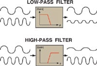 Figure 1. Low-pass filters pass along signals lower than some arbitrary cutoff frequency; high-pass filters pass signals higher than the cutoff frequency |
For a real-world example of the difference between a low-pass and a high-pass filter, consider the bass and treble knobs on your stereo. The bass knob attenuates or enhances low-frequency sounds like drums or tubas, while the treble knob does the same for high-frequency sounds like flutes. The two main defining characteristics of a filter (among many) are the cutoff or corner frequency, and how well it discriminates against signals on the wrong side of that corner.
Now for Some Circuits
Two minutes in and we have already covered theory and applications! Now it's time to see some circuits. Many simple passive filters can be derived by starting from a resistive voltage divider (Figure 2). If you don't know how one of these works, I suggest you enroll in the "Five-Minute Circuit Theory" course and come back next semester. If you already took this course (and remember only P = IV) then I can tell you that a voltage divider's gain (ratio of output voltage to input voltage) is R2/(R1+R2).
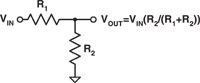 Figure 2. You can derive a passive filter by starting from a resistive voltage divider |
To turn a voltage divider into a filter, you substitute a capacitor or inductor for one of the resistors. This results in a voltage divider where the division ratio becomes frequency dependent. This is because the "resistance" of an inductor can be defined as 2πfLj and that of a capacitor can be defined as 1/2πfCj. If this were a real filter design course we would now combine these expressions with the voltage divider equation to derive frequency-dependent expressions for various filters. Note that these expressions have imaginary values, however, which means complex math. Since this is the five-minute course (and we are three minutes in), let's just skip the math part and take a look at some rules of thumb to describe qualitative behavior.
Rules of Thumb—and Where It Gets Hard
- 1. At DC (frequency = 0), capacitors are open circuit (R = infinity) and inductors are short circuits (R = 0)
- 2. At infinitely high frequency, capacitors are short circuits (R = 0) and inductors are open circuits (R = infinity)
- 3. Resistors are resistors at all frequencies
You can now consider the four cases shown in Figure 3 (page 34) and Figure 4.
Figure 3. Some quick-reference rules of thumb for filters |
Note that we haven't considered the cases where you completely throw out the resistors and just use inductors and capacitors. If you use only inductors and only capacitors, then you get voltage dividers that work everywhere except at DC. If you use both, you wind up with a low-pass or high-pass filter with resonance, which vastly complicates the subject and is therefore taught in Five-Minute Grad School.
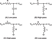 Figure 4. Schematics of the four examples given in Figure 3 |
Find the Corner Frequency
Now that we have low-pass and high-pass circuits, we need to be able to determine what the corner frequency is. For circuits with resistors and capacitors, the corner frequency is:
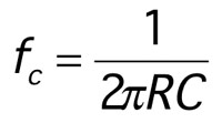 Equation |
For circuits with resistors and inductors: the corner frequency is given by:
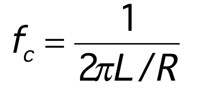 Equation |
Now that we know the corner frequencies of some filter designs, the other big question is how well they discriminate against unwanted signals. The answer is –20 dB/decade. This means that for every factor of 10 you vary the frequency outside the passband, the response also varies by a factor of 10. For example, if you have a low-pass filter that provides a gain of 0.1 to a 100 Hz signal, it will provide a gain of 0.01 to a 1000 Hz signal, attenuating it a factor of 10 more.
Quiz
Extra Final Exam Question: What do you think the circuit in Figure 5 does?
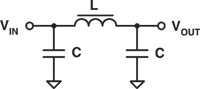 Figure 5. Quiz: What does this circuit do? |
Answer: This is a low-pass filter, specifically called a pi filter. At DC, the capacitors appear as open circuits and the inductor connects input to output. At high frequencies, the inductor opens up and the capacitors short to ground, preventing high-frequency signals from passing.
DING! Class dismissed until next month!