

Last month we discussed a number of simple passive filters in both low-pass and high-pass configurations. Although these filters could reject out-of-band signals, this capability was relatively limited because they all had an attenuation roll-off rate of –20 dB/decade. You will find that many applications require a much greater ability to reject out-of-band signals than that provided by the passive low-pass filters we looked at.
Try Cascading
One obvious way to get better out-of-band rejection is to cascade a number of passive filters together (Figure 1A). The addition of a second stage dramatically increases the rate at which the response drops off (Figure 1B) compared to that of a single RC filter. One drawback of this circuit, though, is that the second filter stage loads down the first, changing its frequency response. One solution is to increase the impedance of the second stage so as to minimize these loading effects. In the example shown, the way to do this is to increase R2 by a factor of 100 to 100 k and correspondingly reduce C2 to 0.001 µF.
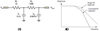 Figure 1. Cascading several passive filters together gives you better our-of-band signal rejection (A); adding a second stage increases the rate at which the response drops off (B) |
Interposing a unity gain amplifier between filter stages (Figure 2) is another way to keep the later ones from loading the earlier ones. This scheme has the advantage of almost completely eliminating loading effects on the first stage. You can also see that it allows you to use comparable impedance levels. A final benefit is that it provides the ability to cascade an unlimited number of stages.
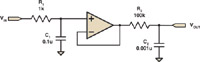 Figure 2. To keep the later filter stages from loading down the earlier ones, try putting a unity gain amplifier between them |
Why You Need an Amplifier
One of the major disadvantages of both the buffered and unbuffered filters described above is that as you add stages, the transition from the pass band (where signals are transmitted) to the stop band (where signals are blocked) gets less and less distinct. This reduces a filter's effectiveness at discriminating among signals with slightly different frequencies. If you take a look back at Figure 1A, you will notice that this transition region, the "knee" of the response curve, is softer in the case of two filter sections compared to the case of the single RC section. While the ultimate attenuation rate of the more complex filters will increase as you get further and further into the stop band, their ability to distinguish among signals of similar frequency near the corner frequency may not improve very much at all.
By using an amplifier to provide feedback, as opposed to merely buffering signals, you can significantly sharpen up the filter's response. The first change is to set up the amplifier so that it provides a gain of >1 (Figure 3A, page 29). You do this by the addition of R3 and R4, and the resulting gain is G = 1 + R4/R3. The next step is to use one of the capacitors (C1) to provide feedback, as opposed to just tying it to ground.
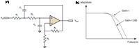 Figure 3. Using an amplifier to provide a gain of >1 for feedback sharpens up the filter s response (A); if you set the gain set to larger values, the feedback loop will tend to make the response sharper (B) |
Where It Gets Interesting
At DC, the capacitors effectively drop out of the circuit, and the output is simply the gained-up version of the input. Note that the DC gain of this circuit is not unity, but is set by R3 and R4. At very high frequencies the capacitors short out, and the output is zero. The interesting part occurs near the corner frequency. One terminal of C1 is driven by the amplifier output. Because of the amplifier's gain, and because R2 and C2 can provide phase shift, the voltage across C1 can be different, both in terms of phase and magnitude, from the input voltage. If you set the amplifier gain to equal 1 (leave out R3), the overall response of this circuit will be similar to that of the circuit of Figure 2. When you set the gain to larger values, however, the feedback loop will tend to make the response sharper (Figure 3B). While you can pick any gain value you care to (really large ones will make the filter unstable), certain values result in filters with well-understood characteristics. For example, using a gain of 1.586 results in a Butterworth filter with a maximally flat pass band and a corner frequency of ½ RC.
DING! Summer session over. Everybody into the pool!
Ed Ramsden, BSEE, a member of the Sensors Editorial Advisory Board, designs sensors for the heavy-truck industry in Portland, OR.