
Traditionally the interaction of solid-state devices with the electromagnetic spectrum has concentrated on detecting perturbations in the magnetic field. Hall Effect sensors, for example, provide reliable detection in a variety of either analog or digital (Schmitt-triggered) applications. In our everyday lives we rely on information encoded into the magnetic flux density field (the B field) to carry data to our digital telephones and TV systems. While Maxwell's equations tell us that wherever we propagate a magnetic field then a corresponding electric field is present, detection and study of this component has been largely ignored.
Electrometers measure the electric charge or electrical potential difference and are essentially voltmeters with an extremely high input impedance such that the current flowing into the device can be considered to be zero. Until recently, electrometers have been notoriously inaccurate and have often used delicate components that were sensitive to mechanical shock and thus easily damaged. The EPIC sensor described in this article is an extremely robust solid-state electrometer with such a high input impedance that it is close to being a perfect voltmeter. Its prospective applications are numerous and the recent announcements and demonstrations of this technology have created a great deal of excitement among the engineering community.
What Is EPIC?
EPIC is an acronym for "Electric Potential Integrated Circuit" but the term has become synonymous with the integrated circuit technology, the sensor itself, and, in a wider context, the physical principles of operation of the device within a system.
EPIC is a noncontact electrometer, meaning that there is no direct DC path from the outside world to the sensor input, a condition that is somewhat analogous to the gate electrode of an MOS transistor. The electrode is protected by a capping layer of dielectric material to ensure that the electrode is isolated from the body being measured. The device is AC coupled with a lower corner frequency (–3dB) of a few tens of MHz and an upper corner frequency above 200 MHz. This response is adjustable and can be tailored to suit a particular application. Such an electrometer cannot be DC coupled because the Earth's electric field close to the surface is ~100–150 V/m.
In single-ended mode the device can be used to read electric potential; used in differential mode it can measure the local electric field; or it can be deployed in arrays to provide spatial potential mapping (locating a conducting or dielectric material placed within free space).
Figure 1 shows a basic block diagram of the EPIC sensor [1]. The size of the electrode is somewhat arbitrary and depends on the input capacitance required for a particular application. For bodies placed close to the electrode, the electrode's size is important and the device operation can be understood in terms of capacitive coupling. For devices that are several meters away, the coupling capacitance is defined only by the self-capacitance of the electrode and the device's response is largely a function of the input impedance as it interacts with the field. This is rather counterintuitive but is a function of the very small amount of energy that EPIC takes from the field in active mode.
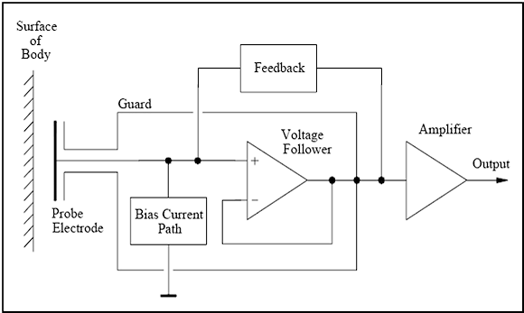 Figure 1. A basic block diagram for the EPIC sensor |
The input resistance to the device can be boosted by using bootstrapping techniques while the input capacitance can be reduced using guarding techniques. The input capacitance can be driven as low as 10–17 F with the input resistance being boosted to values up to around 1015 Ω, thus keeping the interaction with the target field to an absolute minimum and ensuring that all currents are small displacement currents only.
A better understanding of the feedback mechanisms can be obtained by considering the input buffer of the amplifier and its associated impedances as shown in Figure 2. The resistors RG1 and RG2 are used to set the gain of the first stage, which is nominally unity. Cin and Rin represent the input capacitance and resistance native to the amplifier, respectively, and include any parasitic components due to layout or substrate issues. The capacitor Cext models the capacitive coupling to the measurement target.
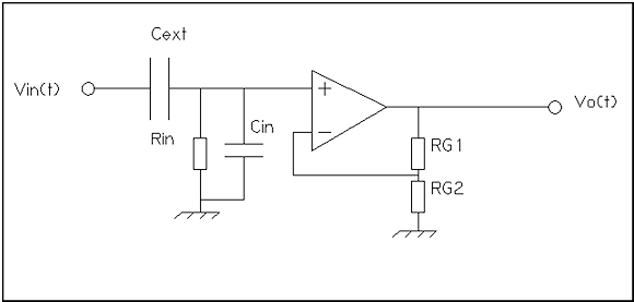 Figure 2. The input (first) stage of the EPIC sensor |
For close coupling (Cext >> Cin) this is usually defined by Equation 1:
| (1) |
where:
| a | = | the equivalent shared electrode/target area |
| d | = | the distance between target and sensor |
| ε0 | = | the permittivity of free space |
| εr | = | the relative permittivity of the dielectric in which the sensor is operating |
For loose coupling (Cext<< Cin) we have the limiting case (self-capacitance) shown in Equation 2:
| (2) |
Where r is the diameter of the sensor plate.
Analysis of the circuit shows us that we have a classic single-pole transfer function as shown in Equation 3:
| (3) |
The Bode plot for this is shown in Figure 3.
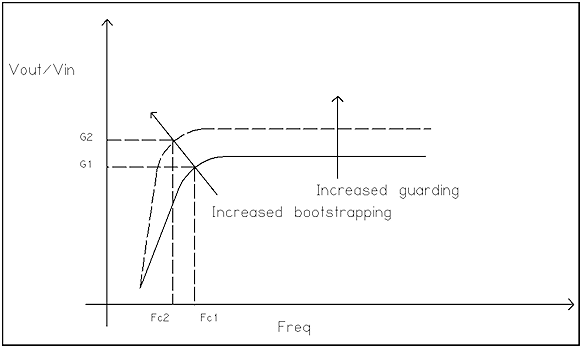 Figure 3. Bode plot for the transfer function of Equation 3 |
The corner frequency (Fc1) can be expressed in Equation 4:
| (4) |
By applying the bootstrapping techniques mentioned earlier, we can control the values for Cin and Rin to give effective values, allowing us to control both the gain plateau and the corner frequency (Fc1 moves to Fc2). The response of the sensor can be further controlled by the design of subsequent stages and positive feedback loops. Thus we have a sensor that can be tailored to suit the particular application at hand.
Figure 4 shows a pair of Plessey EPIC sensors and the associated control box. The control box is an amplifier/filter combination and is used for demonstration purposes only. The electrodes shown here have been tailored for contact ECG measurement but can also be used for remote sensing and other applications.
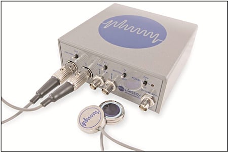 Figure 4. EPIC evaluation kit |
Medical Applications
A great amount of interest has been generated within the medical community where the primary focus is on using EPIC for surface body electrode physiology applications such as electrocardiograph (ECG), electromyograph (EMG), electroencephalograph (EEG), and electrooculargraph (EOG).
The EPIC sensor can be used, for example, as a replacement technology for traditional wet-electrode ECG pads, because it requires neither gels nor other contact-enhancing substances. When the EPIC sensor is placed on (or in close proximity to) the patient, an ECG signal can be recovered. The sensor is capable of both simple 'monitoring' ECG as well as making more exacting clinical diagnostic measurements. In the latter application it can be used as a replacement for the traditional twelve-lead ECG, in which electrodes are placed on the limbs and torso (each pair of electrodes is called a lead and each lead measures the electrical activity of the heart from a slightly different perspective) to achieve a clearer picture of how the patient's heart is working. An array of EPIC sensors placed on the chest can be used to recreate the lead required with resolution as good as or better than that achieved using traditional systems. Figure 5 shows a comparison between the results using EPIC and using traditional wet electrodes for leads II and aVL [2]. These two leads are important in the diagnosis of conditions such as coronary artery occlusion.
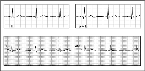 Figure 5. ECG readouts showing the results using EPIC (top) vs. traditional wet electrode ECG (bottom) |
The sensor can also be used for recovering other physiological signals such as those caused by the electrical activity of the eye muscles as one looks left, right, up, or down. These signals have unique signatures; an EOG can be used to track the position of the eyes and therefore produce targeting information for military and gaming applications, for example. Perhaps the most exciting application in the medical field is that of electroencephalography (EEG) where the electrical activity of the brain is recorded. Application of the EPIC sensor to this field is still in its infancy but the potential ability to record identifiable signals against known thought patterns opens up possibilities that currently only exist in science fiction.
Other Applications
Security. Because of EPIC's mode of operation, it can be used to detect any disturbance in the local electric field at distances of up to several tens of meters. The human body, because it acts as a large container of conducting/polarizable material, causes a large perturbation in the electric field and so presents an easily detectable target for the sensor. Sitting a few meters away from the sensor, one has only to raise the sole of one's foot to create a strong signal. Arrays of sensors can be used to provide spatial resolution and therefore the location of a target. Such arrays can also distinguish between humans and quadrupeds because the time signature of the response is a direct function of cadence. Such a system of sensors could perhaps be used for border security in remote areas.
Man-machine interface. The ability of EPIC to resolve signals unique to various muscles or groups of muscles presents opportunities for improved man-machine interaction. For example, a quadriplegic who currently depends on either a unicorn stick or a suck/blow tube to issue commands to equipment within his or her local environment could achieve a faster and more efficient interaction using EPIC for eye tracking and detection of activity in any muscle groups still under voluntary control. Alternatively, because EPIC can assign a unique signature to the use of certain muscle groups, it opens up many possibilities for interfacing with and controlling prosthetic limbs.
Microscopy. EPIC is also a useful tool in the microscopic domain. Small sensors scanning a microchip, for example, can show areas of high or low potential, allowing the user to map the current distribution within metal tracks and other circuit elements. Faults in dielectric materials can also be detected either by passive means (by detecting piezoelectric effects) or by identifying leakage paths in an active circuit.
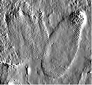 Figure 6. A fingerprint taken from a PTFE insulating plate using an EPIC sensor |
Conclusions
The release of EPIC technology into the wider commercial environment has been talked about as being disruptive. The technology is certainly novel in its operation and opens up a wide range of fields in which EPIC may be applied to provide solutions to diverse engineering problems. In this article we have only touched on a small subset of these. Other potential applications could include building and vehicle health, communications, and seismology. The future for EPIC is an exciting and challenging one. It is my opinion that in years to come, the introduction of this technology will be seen as marking a milestone in sensor technology development.
References
[1] Private communication from Professor Robert Prance, University of Sussex, U.K.
[2] C. J. Harland, N. S. Peters, et al., "A compact electric potential sensor array for the acquisition and reconstruction of 7-lead ecg without electrical charge contact with the skin," Physiol. Meas. 26 (2005) 939–950, doi:10.1088/0967-3334/26/6/005
[3] P. Watson, R. J. Prance, and S. T. Beardsmore-Rust, "Latent electrostatic fingerprints and their decay: towards a forensic timeline," submitted to Nature.
ABOUT THE AUTHOR
Dr. Sean Connor is Applications Engineering Manager for Plessey Semiconductors Ltd. He can be reached at +44 (0)1793-518007, [email protected].