
For years, aircraft assembly and structural component manufacturers have been using traditional contact methods such as plastic shims, feeler gauges, and step gauges to measure gaps during the production and final assembly of commercial and military aircraft. Hundreds of gaps between metal/metal, metal/carbon-fiber-reinforced polymer (CFRP), and CFRP/CFRP surfaces must be measured and controlled during aircraft production to determine whether liquid or solid shimming is required. These gaps can be found in a wide variety of applications (such as those shown in Figure 1) located throughout the aircraft structure.
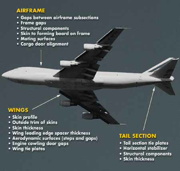 Figure 1. Typical aircraft gap measurement locations |
The Impetus for New Gap Measurement Techniques
Due to the increased adoption of standardized process improvement methods such as SPC and Six Sigma, aircraft structural component manufacturers from Alenia to Lockheed are adjusting the output specifications required from their measurement instrument suppliers. The new standards require the measurement, data capture, and documentation of an increasing number of physical measurements such as gaps, holes, and parallelism during their manufacturing and assembly processes. Traditional gap measurement methods such as feeler gauges and plastic shims cannot meet the new quality specs for accuracy and repeatability and cannot automatically record and store error-free data.
These old methods have limitations and reliability problems: shims and feeler gauges suffer from inadequate accuracy; plastic shims can vary in thickness by 7.6 µm; and both shims and feeler gauges cannot meet required operator-to-operator repeatability levels. In addition, over time shims experience wear from constant rubbing against hard surfaces, reducing their accuracy and also potentially causing damage to the target surfaces.
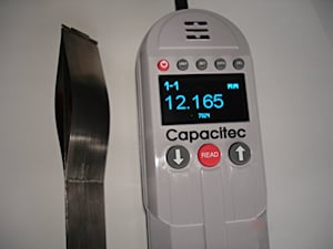 Figure 2. Photo of GapmanGen3 with remote spring contact wand |
Users now commonly perform analysis of variance (ANOVA) and gauge repeatability and reproducibility studies (Gauge R&Rs) to compare traditional measurement methods to more modern ones such as digital capacitive noncontact gap sensor instruments. A leading aircraft structure manufacturer recently tested and concluded that feeler gauges could no longer meet their Six Sigma requirements, forcing them to change their measurement methods. Gauge R&R analyses found that mechanical gauges resulted in 45% measurement dispersion—greater than the required 30% dispersion minimum for Six Sigma—in contrast to the 20% or better dispersion achieved using Capacitec gap gauges. They opted to use a Gapman capacitive gap measurement system that they call their "electronic feeler gauge" (Figure 2).
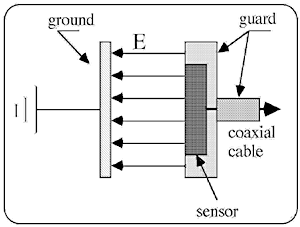 Figure 3. Capacitive technology |
Capacitive Gap Measurement
Capacitance measurement is the core technology used by Capacitec for its line of noncontact displacement, gap, hole, and parallelism sensors and sensor systems. Because capacitive reactance is proportional to the distance between the capacitive sensor and the target, we can make these distance measurements by measuring the variation of the capacitance between the sensor and its target (Figure 3).
Aircraft structure gaps are measured using two capacitive displacement sensors mounted back-to-back at the end of a flat wand. Each sensor has a central sensing element with a typical diameter of between 2–5 mm, depending on the gap range required. The larger the sensor diameters, the larger the linear range of the gap sensor wand. A ring guard layer surrounding both sensors serves to focus the capacitive charge field to a grounded target. Each sensor has a 100% shielded coaxial cable.
When positioned parallel to an earth-grounded or conductive target, the sensor measures a capacitance proportional to the air gap. When the signal is input to a specialized amplifier, the output range can be linearly apportioned over a 0–10.000 VDC signal. The resulting output has a ratio of 1:10,000; e.g., a full-scale range of 0.254 mm divided by 10,000 yields an output resolution of 250 nm/mVDC.
Sensor Wand Development
Over the years, Capacitec has developed various types of sensor wands to meet specific user needs.
Noncontact semi-rigid sabres. In the 1980s, nuclear fuel rod manufacturers were using mechanical contact gauges to measure thin gaps between the hundreds of individual rods in fuel rod assemblies (Figure 4). Babcock & Wilcox, Westinghouse, Areva, and others were dissatisfied with the reliability, accuracy, and overall performance of these mechanical gauges and approached Capacitec to develop a better method.
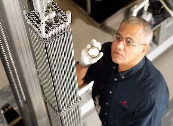 Figure 4. Typical nuclear fuel rod bundle |
The resulting design consisted of two matching capacitive noncontact displacement sensors on opposite sides of a metal sabre and calibrated to two custom capacitive amplifiers. After the fuel rod bundles were assembled, these semi-flexible, half-meter-long gap measurement sabres were automatically inserted between rows of 16 fuel rods at several locations along the fuel rod bundle's 6 m height. Based on the new design's reliability, repeatability, high accuracy, and durability the Capacitec noncontact gap measurement system is now the standard measurement technology for fuel rod manufacturers around the globe.
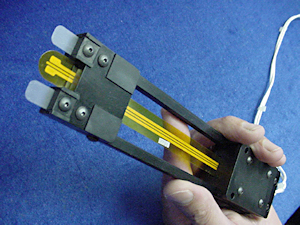 Figure 5. Very thin flexible wand with wand positioning holder |
Flexible sensor wands. The demand for more uniform and thinner film products accelerated within the thin-film liquid coating industry, inviting manufacturers such as 3M, Kodak, and DuPont to seek out new methods to control the coating consistencies across their 2–3 m specialized coaters. Research found a direct relationship between the consistency of the coating thickness and the ability to set very accurate gaps in the coater dies prior to production. Capacitec was approached to develop new, customized, very thin and flexible gap sensor wands to replace plastic shims.
The resulting slot die coater gap measurement system allowed users to maintain ±0.25 µm uniformity across coater dies leading to better control of nanometer-level coating thicknesses (Figure 5). These flexible Kapton gap sensor wands were further adapted to operate with the company's Gapman instruments to accurately and automatically measure gaps in aircraft structures.
Self-grounded semi-rigid contact sabres. Designed in response to GE PowerGen's request to develop a better way to measure gaps between gas turbine fan blades and the exterior enclosure, Capacitec developed self-grounded semi-rigid contact sabres. This application required the measurement of the gaps between a conductive and a nonconductive target. The resulting spring contact wand uses matching upper and lower self-grounded moving metal springs to act as the conductive target. This system eliminates the need to ground targets while offering reliable gap measurement where one or both targets are nonconductive (Figure 6).
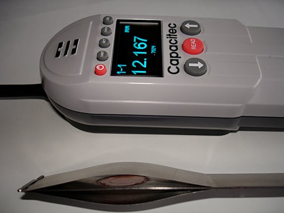 Figure 6. The GapmanGen3 with a remote spring-contact sabre |
Sensor Selection
The selection of the appropriate capacitive gap sensor wand model is application-driven and based on the following factors: minimum gap, gap range, target material combinations (metal/metal. metal/CFRP, CFRP/CFRP), and difficulty of access to target. There are dozens of standard models of both flexible wands and spring-contact sabres to choose from, as well as the option of developing custom models according to customer needs.
Flexible wands. Kapton flexible wands (Figure 7) are typically used to measure the thinnest gaps and in situations where the flexibility of the wand improves access to the target. The Model GPD-(3X1)I-A-225 offers a gap measurement range from 0.15–1.0 mm while the Model GPD-4.5 (0.0075)-A-250 has a gap measurement range of 0.20–3.0 mm; other models can be specified for ranges up to 10 mm.
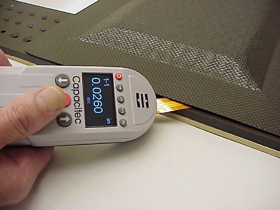 Figure 7. A GapmanGen3 with an integral flexible wand measuring very thin gaps between two pieces of CFRP |
Self-grounded spring-contact wands. These wands (as shown in Figures 2 and 6) are typically used in applications where: one or both targets are nonconductive; a target size is <1 mm; the surface or shape of the target is irregular. They are the most popular choice for CFRP/CFRP applications where the minimum gap is >0.64 mm. The spring-contact wand Model GPD-5 (0.22)-A-150 has a range of 0.64–3.0 mm while the range of the GPD-10 (.034)-A-350 is 0.86–10.0 mm.
For larger gaps such as those between trailing edge flaps and the wing, where the gaps typically run 20 mm ±5 mm, a custom wand can be made by building a noncontact or spring-contact wand onto a 15 mm shim with a set of GPD-10 sensors to give a measurement range of 15–25 mm. The selection of integral or remote wand mounting configurations for use with the Gapman is shown in Figure 8.
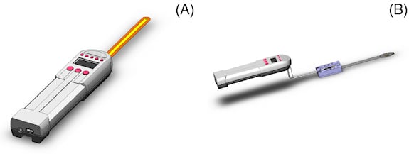 Figure 8. Sensor wand mounting configurations with an integral flexible wand on the left (A) and a remote spring-contact wand (B) on the right |
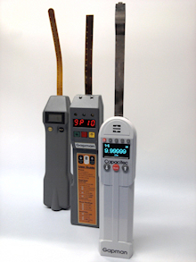 Figure 9. Gapman generations (from left to right) showing the GapmanGen1 (analog), the GapmanGen2 (digital), and the GapmanGen3 (serial/wireless) |
The Gapman
The Gapman has gone through three generations as seen in (Figure 9). The GapmanGen2 model was introduced with flexible wands in 1996, with the later introduction of remote vs. integral configurations and the availability of spring-contact wands. Today most commercial and military aircraft manufacturers use the GapmanGen2 to measure and control gaps that typically range from 0.20–3.0 mm. In the assembly of tail sections, a GapmanGen3 with flexible wand is used to measure gaps 20 cm inside of the subassembly (Figure 10).
The self-grounded spring-contact saber is often used to measure gaps between targets where one or both sides are composed of CRFP. In another application example, gap readings from the Gapman are sent to a CNC machine that manufactures custom shims that perfectly fit in the void between two structural components of the aircraft.
The GapmanGen3 was introduced in late 2010. Among the main design enhancements of this next-generation device are higher resolution output (0.254 µm) with ±0.05% F.S. (12.7 µm) typical accuracy with a GPD-5F wand; >10,000 data point logging and storage capabilities; doubled battery life (now 22 hr. min. with 3 AA lithium batteries); and simplified PC-based software for controlling device functions and for offloading gap measurement data via USB or the soon-to-be-released Zigbee option.
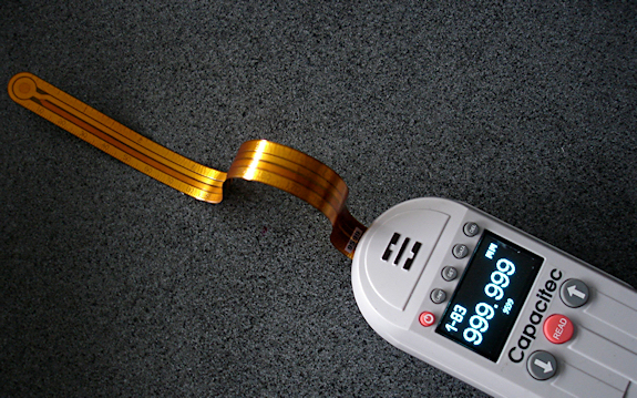 Figure 10. GapmanGen3 showing flexible wand |
The 56 by 220 by 28 mm, 454 g GapmanGen3 features the same high-precision dual-capacitive sensing technologies for position-compensated measurements as its predecessor. It can also allow, using backwards-compatible standard and custom sensor probes, insertion into gaps as thin as 0.150 mm.
The GapmanGen3 records and stores data points for transfer to SPC systems, in support of Six Sigma and other quality systems. With its user-friendly enhancements, the GapmanGen3 can be used effectively to measure gaps within a wider range of aircraft applications, including aircraft manufacturing and assembly operations; mating metal and rigid composite surfaces (CFRP); and aircraft engine construction and rebuilding. Other applications include flexible solar panel lamination; coater roller-to-roller parallelism; film production; and any other noncontact gap measurement applications characterized by minimal gap tolerances and complex assemblies.
ABOUT THE AUTHORS
Bryan Manning ([email protected]) is Commercial Director for Capacitec Europe and Robert L. Foster is founder and President of Capacitec Inc., Ayer, MA. They can be reached at 978-772-6033, [email protected].