
A variety of industries—aerospace, oil and gas production, semiconductor manufacturing, automotive, military, and medical—require the accurate, repeatable, and reliable measurement of linear and rotary motion and position. Applications include monitoring the movement of linear shafts and pistons, rotating gears and wheels, pivoting joints, and other tasks that involve the motion of a mechanical component in a piece of equipment relative to another. These applications can be as small as miniaturized focus modules for biometric ID or as large as motion control for a CNC gantry-type coordinate measuring machine.
There are a variety of options—both contact and noncontact—available to measure linear and rotary motion. Options for contact systems include potentiometers and mechanical proximity switches. Noncontact systems use optical/laser, magnetostrictive, capacitive, inductive, ultrasonic, and other measurement principles. Of these, the noncontact options offer the benefits of long life, high reliability due to limited component wear and degradation, limited damage that may occur from contact with a work piece, and the ability to encapsulate or pot the component pieces of the measuring system to protect them from the environment. Although these measuring systems can offer a high degree of system accuracy, that high accuracy comes at a high price. There is a market need for a noncontact system that can measure linear and rotary motion with a high degree of accuracy but at a lower cost.
Hall cell technology offers one such option. Physicist Edwin Hall discovered the Hall effect in 1879. He discovered that when an electrical conductor or semiconductor with current flowing through it in one direction was subjected to a magnetic field perpendicular to the direction of the current flow, a voltage could be measured across the conductor at a right angle to the current path (Figure 1).
 Figure 1. The Hall effect principle |
This induced voltage has three key characteristics: (1) its strength is proportional to the strength of the current in the conductor and to the strength of the magnetic field passing through the conductor; (2) the change in the induced voltage that occurs with changes in the current and magnetic field strength is repeatable; and (3) the phenomenon is measurable. These basic principles can be used to create a low-cost noncontact sensor to measure linear and rotary motion. To measure the movement of one part or surface relative to another, a Hall sensor is attached to one part and a magnet is attached to the other. As the two objects change position relative to each other (with either a linear or rotary motion) this change in position can be directly measured by measuring the change in the induced voltage across the Hall sensor, without contact.
When using Hall sensors to measure linear position, limitations in the magnetic field produced by a traditional bipole axially (Figure 2) or diametrically (Figure 3) magnetized magnet with single North and South poles result in a limited measurement range and accuracy. For instance, if we consider the linear motion Hall sensors from austriamicrosystems AG (ams), the magnetic field strength of the traditional bipole magnet drops below the required minimum for the sensors within 15–20 mm on either side of the magnet, depending upon the specific magnet used. In contrast, if we use a multipole magnet (Figure 4) we can achieve the required field strength over a greater distance through its continuous pattern of repeating North and South poles. When using a multipole magnet, the maximum possible linear measurement is only limited by the length of magnet that it is physically possible to make.
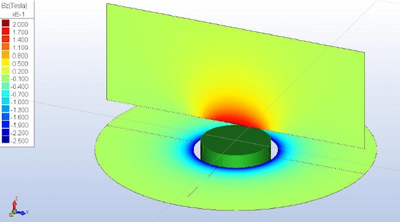 Figure 2. Magnetic field of an axially oriented magnet |
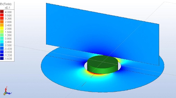 Figure 3. Magnetic field of a diametrically oriented magnet |
 Figure 4. Magnetic field of a multipole strip magnet |
Development Issues
The development of high-accuracy, low-cost, linear and rotary position measurement systems requires the development of both Hall sensors that can use multipole magnets and the appropriate multipole magnets themselves. For accurate linear motion and rotary angle sensing, ams has developed a family of noncontact, high-resolution magnetic encoders. These sensors offer measurement resolution down to <0.5 µm and require a multipole strip or ring magnet with a pole length of 1.0 mm, 1.2 mm, or 2.0 mm, depending on the sensor, for proper sensor operation. For an overall measurement system to be successful, the magnets must be made using a material that can be magnetized to the required field strength. The material must be capable of being supplied cut to different lengths as required by the end user. Perhaps most important, the magnetizing process must result in a highly accurate and repeatable pole length.
Development Results
Dexter Magnetic Technologies has developed a multipole strip magnet with pole lengths of 1.0 mm, 1.2 mm, or 2.0 mm, and a pole-length accuracy within 2.0% of a pole pair (40 µm for a 1.0 mm pole length magnet). Different magnet materials were investigated and the final selection was a flexible ferrite material with an energy grade of 1.4 MGOe that exhibits the desired magnetization. The material selected also possesses the key ease-of-cutting characteristic while offering a low cost. Of the two standard sizes developed and tested, one is 1.5 mm thick by 9.5 mm wide; the other is 0.76 mm thick by 3.18 mm wide. Both magnets can be magnetized to produce the required 5–60 mT field at the surface of the sensor. The magnet ha an operating temperature range of –40°C to 80°C and a linear coefficient of thermal expansion of 5 × 10⁻⁵° C–1 (Figure 5). For practical application, the magnets can be produced with a pressure sensitive adhesive applied to the nonmagnetized side to allow the magnet to be mounted on a range of surface materials and textures. The flexible ferrite material also allows the reliable production of magnets up to 5000 mm long or longer.
 Figure 5. Configuring multipole magnets for use with encoders |
During development of the multipole magnet it became apparent that a purpose-designed test fixture was needed to test the magnet in a linear measurement application. When the Hall sensor/magnet system measured a linear distance of one pole pair, the measurement accuracy was required to be within 2%. The custom test fixture (Figure 6) was initially designed and built to test the 1.0 mm pole length magnet design.
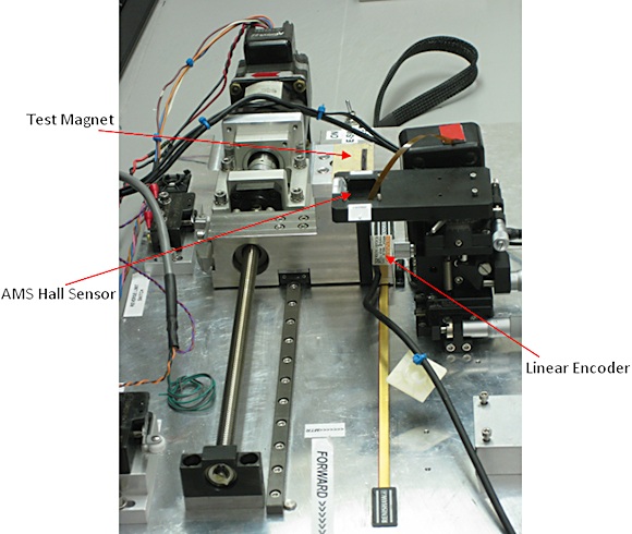 Figure 6. Test fixture |
The magnet being tested is mounted on a small sample platform, 0.5 mm below a Hall sensor, which is attached to a stepper-motor-controlled carriage. A Renishaw optical encoder, consisting of an RGH24 readhead with 50 nm resolution and an RGS20-S linear scale with 20 µm graduations, is used to measure the magnet's linear movement along the test fixture during testing. This linear scale is attached to the base of the testing fixture. The readhead is used to precisely measure the linear position of the test platform and magnet as it moves along the scale. An ams NSE5310 Hall sensor is used to measure the magnetic field of the test magnet and its linear position as the sample platform moves along the test fixture. The NSE5310 magnetic linear encoder provides instant indication of the magnet position with a resolution of 0.488 µm per step (12-bit (4096) over a 2.0 mm pole pair).
Test results proved that magnetic end effects and the physical distortion of the magnetic material caused by cutting the magnet to length disturbed the magnetic profile of the first few pole pairs. However, beyond the first few pole pairs the magnet demonstrated a pole-length accuracy within 2.0% of a pole pair (40 µm for a 1.0 mm pole length) (Figure 7).
 Figure 7. A graph of pole-pair to pole-pair measurements. The X axis shows the travel in mm along the magnet while the Y axis provides the % deviation between each pole-to-pole pair (Click image for larger version) |
Next Steps
The test fixture will be refitted with the ams AS5306 and ams AS5304 Hall cell linear magnetic encoder to allow testing of the 1.2 mm pole length and the 2.0 mm pole length multipole magnets, respectively. These ams sensors were selected because each sensor/magnet combination is a unique partnering according to pole length (i.e., 1.2 mm and 2.0 mm).
ABOUT THE AUTHOR
Steven Gauthier, P.E., is Business Development Manager for Dexter Magnetic Technologies Inc., Elk Grove Village, IL. He can be reached at 847-952-6430, [email protected].