

As users have benefited from distributed processing to separate tasks and enable higher performance for tasks in computing systems, many are applying similar concepts to test systems. Some applications, such as systems with equipment residing in multiple locations or systems that have limited room such as in-vehicle tests, physically require a distributed system. These systems have the additional benefit of increasing your processing power and I/O bandwidth.
To successfully implement a distributed system, you need to consider three factors: required measurement functionality, capabilities of the instrumentation buses, and software.
Instrument Selection
When selecting an instrument, first make sure it meets your requirements in terms of accuracy, sampling rate, frequency, dynamic range, etc. Stand-alone instruments provide a fixed set of functions the vendor has defined for the system. Modular instrumentation systems take advantage of software processing to provide additional measurements based on information provided by the modular hardware. The software-defined approach affords greater flexibility than vendor-defined box instruments and, because it is built on PC technologies, has advanced in capability at a much faster rate.
 Key to Abbreviations |
The Instrumentation Bus
The instrumentation bus affects your ability to meet distribution, locality, and performance needs. When designing distributed systems, many people first think of distribution needs—physical requirements, remote locations, and connectivity. For example, your test application might require a distributed system because it has to satisfy packaging size and ruggedness constraints. For in-vehicle testing, you might select remote control of a small PXI or NI's CompactDAQ system (www.ni.com/dataacquisition). This component could be located within the vehicle, and the rest of the system connected locally to the computer interface.
Other applications might require components at various locations, and their data would need to be correlated and synchronized. For instance, creating an acoustic map to characterize the noise made by a plane flying over a designated area would require a distributed test system. You could solve this application using multiple remote PXI systems that are controlled and synchronized from a host computer. For controlling remote systems, you need to consider the programming connectivity options available and their reliability and ease of use. When creating a local system to control tests, review results, and log data from a remote machine, you should evaluate the protocols to find the one that best suits your needs. For instance, NI LabVIEW supports a variety of protocols including TCP/IP, HTTP, and remote panel connection that allows you to control a program through a Web browser. Evaluating how the instrumentation bus supports physical restrictions, synchronization across different locations, and remote connectivity should be factors in creating a distributed system.
Locality refers to placing measurement components physically close together and is determined by considerations including control-loop rates, synchronization, and throughput. For instance, one of the major factors of a control system is the rate to complete a cycle of acquiring, processing, and, in response, outputting a signal. Although the computer processor and the number of instructions limit maximum loop frequency, you can achieve faster control-loop rates through hardware timing and triggering. In addition, many applications require hardware synchronization to ensure that measurement signals are properly correlated. Due to clock drift and start latency, software synchronization does not provide timing accurate enough for many applications. Through hardware synchronization, however, you can ensure that signals are synchronized up to the sub-nanosecond level. Critical hardware synchronization features include a reference clock that synchronizes all peripherals and trigger lines to allow parallel event handling. Triggers are essential for synchronous events such as starting two devices simultaneously as well as for asynchronous events such as handshaking and sequencing.
Another locality consideration is bus throughput. Higher throughput rates are important for applications that send large amounts of data or require data streaming among components. The ability to meet locality needs is largely dependent on bus capabilities.
The instrumentation bus also affects performance. A useful way to compare the performance of one bus to another's is to evaluate the latency and bandwidth. Latency measures the delay of transmission of data across a bus, and bandwidth measures the rate at which data are sent across the bus, typically in megabytes per second. Latency directly impacts applications such as digital multimeter measurements, switching, and instrument configuration, as well as accuracy when synchronizing events. Higher bus bandwidth is important for applications such as waveform acquisition and generation. Figure 1 compares the latency and bandwidth of various instrumentation buses.
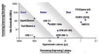 Figure 1. Bus latency and bandwidth affect overall system performance |
A variety of instrumentation buses are available, each with its own strengths. USB has become a popular communication bus choice for stand-alone instruments because its widespread availability on PCs and plug-and-play ease of use allow engineers to quickly connect and configure USB-based instruments. In addition to easy connectivity, you can achieve a maximum transfer rate of 480 Mbps with USB 2.0. Adding to the growing availability of USB instrumentation, the National Instruments CompactDAQ USB data acquisition system takes advantage of Hi-Speed USB, modular design, and flexible software to provide a fast and accurate system with a wide scope of I/O options.
LAN, a mature technology, has been used for many years in test applications. Able to support longer distances, LAN is well suited for distributed applications or remote monitoring. Future generations will improve bandwidth, but latency will only see incremental change. As a result, LAN will continue to be most appropriate for applications with modest throughput requirements such as low-speed distributed data-logging and conventional instrument control.
The PCI bus offers a number of advantages over previous bus implementations, including low latency and high bandwidth at 132 MBps. By combining PCI electrical-bus features with rugged, modular packaging and specialized synchronization features, PXI provides a high-performance, low-cost platform. PXI adds a 10 MHz reference clock, an 8-line trigger bus, and star trigger lines that provide dedicated trigger lines with intermodule skew within 1 ns. To meet the needs of bandwidth-intensive PC applications, PCI Express, an evolution of PCI with complete software compatibility, provides a basic communication lane of 250 Mbps up to 4 Gbps in each direction; this link provides dedicated bandwidth to each slot, as opposed to the shared bandwidth of PCI. PXI has integrated PCI Express into the backplane; PXI Express, an extension of the PXI platform, increases the available PXI bandwidth from 132 MBps to 6 GBps for a more than 45 x improvement while maintaining software and hardware compatibility with PXI modules. This enhanced performance opens the way to new application areas, many of which were previously served only by expensive and proprietary hardware.
Integrated Software Framework
Given the variety of instrumentation buses and their assorted features, it is paramount to use an integrated software framework to combine instruments that meet your requirements and combine them into one ADE. A software framework using LabVIEW and Measurement & Automation Explorer (MAX) delivers a distributed system consisting of PXI, CompactDAQ, and a stand-alone instrument. This system uses the stand-alone instrument for specialized needs, CompactDAQ for data acquisition, and a PXI system for high-performance dynamic signal acquisition as well as control of the entire system. Without an integrated framework, it would be difficult to combine these buses into one system.
The first layer of the framework, measurement and control services, provides support for various bus technologies through a configuration manager, hardware drivers, and flexible high-level APIs. Figure 2 shows how MAX provides an interface to view and configure all of the devices (PXI, CompactDAQ, and LAN) and create and edit channels, tasks, and interfaces. MAX also provides system diagnostics to differentiate between hardware and software debugging issues. Here, having a device driver alone is not sufficient; the driver should offer fast performance, programming flexibility, a consistent and scalable API, and seamless ADE integration so that the software controlling the devices appears only as part of the ADE.
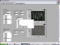 Figure 2. Measurement and control services software simplifies a hybrid system by providing an integrated environment to hardware of all buses as well as perform initial tests |
The second layer of the software framework, the ADEs, should not only leverage the measurement and control services layer, but also provide ease of use, scalability, programming flexibility, and tools for developing distributed applications. Figure 3 shows the way LabVIEW builds on the configurations set in MAX and how, through interactive assistants, code generation, and the ability to interface with any measurement hardware, it provides rapid development for this distributed application. It also offers tools for developing a distributed application from low-level TCP/IP programming APIs to high-level tools such as remote panel connection.
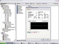 Figure 3. An integrated software framework uses the configuration handled through measurement and control services to simplify programming in the application development environment |
Centering your distributed system on an integrated software framework gives you the flexibility to integrate multiple buses in a hybrid system. By applying the software framework, you gain the freedom to meet functional, performance, distribution, and locality requirements by maximizing the strengths of each bus. This framework provides an integrated environment for configuration and testing instruments as well as rapid test development with tools for developing distributed applications.
Faya Peng, BSEE , can be reached at National Instruments, Austin, TX; 512-683-6754, [email protected], www.ni.com.