

A transducer is only as good as the signal it initiates through a measurement system. Important design decisions affecting human lives and costly structures (e.g., automobiles, aircraft, and buildings) frequently depend on the analysis of these signals. To make intelligent decisions, it is critical to perform measurement uncertainty analysis on the signal. When using transducers where their operating conditions vary with time and/or location, the analysis can be performed only after several requirements have been fulfilled. First and foremost, the transducers, as well as the measurement systems they operate with, must have been designed using good practices. These include adequate low- and high-frequency response and data-sampling rates, appropriate anti-aliasing filter selection, and proper grounding and shielding. In addition to these requirements, performing data validation is necessary to establish that each transducer responds only to the environmental stimulus that it is intended to measure.
Placebos and Data Validation
For piezoelectric transducers, "placebo transducers" (IEST-RP-DTE011.1) enable data validation. The referenced IEST standard defines a placebo transducer as "identical to a 'live' unit in every parameter except for mechanical sensitivities." The placebo transducer should respond only to extraneous environmental factors. Ideally, its output would be zero. Any signal output other than zero indicates that the signals from the "live" transducers can be corrupted.
Some examples of test environments where validation should be performed include flight tests, highly hazardous testing (e.g., blast and munitions), and electrodynamic shaker testing. In the last example, in addition to acceleration, the shaker produces (as a minimum) temporally and spatially varying magnetic fields.
Transducers respond to their environment in every way they can. For example, accelerometer specifications include their response to thermal, acoustic, strain, and radiation stimuli, to name just a few. While accelerometers must have their response to acoustic pressure specified, pressure transducers must have their response to acceleration specified. Thus, one transducer's desirable response becomes another's undesirable response.
Transducer manufacturers try to minimize the effect of these undesirable responses in the design process, but they can never completely eliminate them. Undesirable responses can cause a change in transducer sensitivity or result in additive, spurious signals at the transducer's output attributable to thermoelectric, electromagnetic, triboelectric, and other self-generating noise phenomena. Because the test or instrumentation engineer has the best understanding of the test environment, he or she becomes responsible for validating the data. The transducer manufacturer can assist by supplying "placebo" transducers to support the validation process.
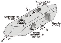 Figure 1. Quartz boule |
Manufacturing Process
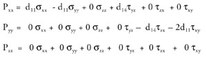
Consider how placebo transducers are manufactured. Figure 1 (page 28) shows a boule of quartz from which piezoelectric elements are cut to be used in the manufacture of force, pressure, and acceleration transducers. The boule's piezoelectric properties vary according to the direction of the cut, as illustrated by Equation 1. Note that the third equation in the set shows that there is one direction (Z axis) that produces no piezoelectric output. Cuts along this axis provide the quartz for placebo transducers.
 Equation 1 |
Unlike piezoelectric transducers used to measure pressure and force, which almost exclusively use quartz, many accelerometers use ceramic-based materials for their sensing elements. In this application, the ceramics are produced by complex manufacturing processes. To behave in a piezoelectric manner, the ceramics must have a high poling voltage placed across their electrodes at a high temperature during the final stages of their manufacture (Figure 2). If the poling is intentionally skipped, the process produces an inert sensing element, which can be used in a placebo transducer. Neither the Z-cut quartz nor the unpoled ceramic placebo transducers can produce a piezoelectric output. However, they do respond in the same manner as a "live" transducer to the undesired environmental factors described previously.
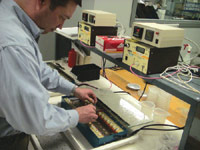 Figure 2. Poling ceramics |
Implementations
Let's look at a couple of examples of successful implementations of placebo transducers. Figures 3A and 3B, respectively, show the response of a placebo and an adjacent live transducer on a building subjected to an explosive blast. Both accelerometers use integral electronics (IEPE or ICP). There is nothing about the highly complex signal shown in Figure 3B (from the live transducer) that imparts confidence in the data. However, the zero output from the placebo transducer in Figure 3A—even with its vertical scale expanded by a factor of 8 with respect to that of Figure 3B—builds confidence that the active, or live, transducer is properly responding to acceleration.
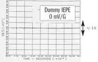 Figure 3a. Placebo transducer |
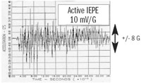 Figure 3b. Live transducer |
Figures 4A and 4B will further illustrate the value of integrating placebo transducers into a test. In this case, a weapons test was performed in which two sets of three live accelerometers and one placebo were assigned to individual telemetry transmitters. The data recorded during the test were noted to be anomalous because of non-zero outputs from both placebo transducers. An investigation was performed to determine the cause of the anomalous data. Figure 4 shows the results of the investigation.
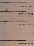 Figure 4A. Transmitter 1; 239.4 MHz |
In Figures 4A and 4B, the uppermost three records are from live accelerometers, and the bottom record in each is from a placebo accelerometer. The frequencies of each telemetry transmitterare shown only for record identification. During post-test analysis, the accelerometers on the 239.4 MHz transmitter were removed from the system, mounted to a metal plate, and struck with a hammer, with the results shown. The live accelerometers generated data, as did the placebo. In addition, signals were emitted from all the accelerometers (the live accelerometers and the placebo) on the 248.6 MHz channel, even though the accelerometers did not experience the hammer blow. A ground loop was found to be the culprit. Design corrections to the measurement system were made so that the test could be repeated and valid data subsequently recorded.
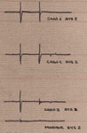 Figure 4B. Transmitter 2; 248.6 MHz |
Although the previous examples focused on acceleration data, placebo transducers are equally useful in dynamic testing, irrespective of whether force, pressure, or acceleration measurements are required [1]. Please consider their routine use.
1. Walter, Patrick L., "Air-Blast and the Science of Dynamic Pressure Measurements," Sound and Vibration, December 2004, pp. 10-16.
Patrick L. Walter, PhD, can be reached at PCB Piezotronics Inc., Depew, NY; 817-257-6318, [email protected] , www.pcb.com.