
Last month we discussed the basics of capacitive sensing, both how the sensor works and explanations of the important terminology. Now it's time to apply this knowledge and explain how to optimize the performance of capacitive sensors.
Effects of Target Size
The target size is a primary consideration when selecting a probe for a specific application. When the sensing electric field is focused by guarding, it creates a slightly conical field that is a projection of the sensing area. The minimum target diameter is usually 130% of the diameter of the sensing area. The further the probe is from the target, the larger the minimum target size.
Range of Measurement
The range in which a probe is useful is a function of the size of the sensing area. The greater the area, the larger the range. Because the driver electronics are designed for a certain amount of capacitance at the probe, a smaller probe must be considerably closer to the target to achieve the desired amount of capacitance. In general, the maximum gap at which a probe is useful is approximately 40% of the sensing area diameter. Typical calibrations usually keep the gap to a value considerably less than this. Although the electronics are adjustable during calibration, there is a limit to the range of adjustment.
Multiple Channel Sensing
Frequently, a target is measured simultaneously by multiple probes. Because the system measures a changing electric field, the excitation voltage
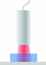 Figure 10. Nonconductors can be measured by passing the electric field through them to a stationary conductive target behind |
Effects of Target Material
The sensing electric field is seeking a conductive surface. Provided that the target is a conductor, capacitive sensors are not affected by the specific target material; they will measure all conductors—brass, steel, aluminum, or salt water—as the same. Because the sensing electric field stops at the surface of the conductor, target thickness does not affect the measurement.
Measuring Nonconductors
Capacitive sensors are most often used to measure the change in position of a conductive target. But capacitive sensors can be very effective in
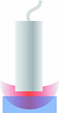 Figure 11. Without a conductive target behind, a fringe field can form through a nearby nonconductor allowing the nonconductor to be sensed |
It is not always feasible to have a reference target in front of the probe. Often, measurements can still be made by a technique called fringing (Figure 11). If there is no conductive reference directly in front of the probe, the sensing electric field will wrap back to the body of the probe itself. This is called a fringe field. If a nonconductive material is brought in proximity to the probe, its dielectric will change the fringe field; this can be used to sense the nonconductive material. The sensitivity of the sensor to the nonconductive target is directly proportional to the dielectric constant of the material. Figure 12 lists some common dielectric constants.
| Material | Dielectric Constant Relative (ξr) |
| Vacuum | 1.0 |
| Air | 1.0006 |
| Epoxy | 2.5–6.0 |
| PVC | 2.8–3.1 |
| Glass | 3.7–10.0 |
| Water | 80.0 |
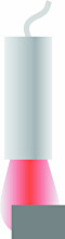 Figure 13. An undersized target causes the sensing field to extend to the sides of the target, introducing error |
Accuracy requires that the measurements be made under the same conditions in which the sensor was calibrated. Whether it's a sensor calibrated at the factory, or one that is calibrated during use, repeatable results come from repeatable conditions. If we only want distance to affect the measurement, then all the other variables must be constant. The following sections discuss common error sources and how to minimize them.
Target Size. Unless otherwise specified, factory calibrations are done with a flat conductive target that is considerably larger than the sensing area. A sensor calibrated in this way will give accurate results when measuring a flat target >30% larger than the sensing area. If the target area is too small, the electric field will begin to wrap around the sides of the target, meaning that the electric field extends farther than it did in calibration and will measure the target as farther away (Figure 13). In this case, the probe must be closer to the target for the same zero point. Because this distance differs from the original calibration, error will be introduced. Error is also created
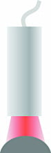 Figure 14. A curved target will require that the probe be closer and the sensitivity will be affected |
If the distance between the probe and the target is considered the Z axis, then an additional problem with an undersized target is that the sensor becomes sensitive to the X and Y location of the probe. Without changing the gap, the output will change significantly if the probe is moved in either the X or Y axis because less of the electric field is going to the center of the target and more is going around to the sides.
Target Shape. Shape is also a consideration. Because the probes are calibrated to a flat target, measuring a target with a curved surface will cause errors (Figure 14). Because the probe will measure the average distance to the curved target, the gap at 0.0 V will be different from the gap at 0.0 V when the system was calibrated. Errors will also be introduced because of the different behavior of the electric field with the curved surface. In cases where a nonflat target must be measured, the system can be factory calibrated to the final target shape. Alternatively, when flat calibrations are used with curved surfaces, multipliers can be determined to correct the measurement value.
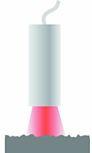 Figure 15. Rough surfaces will tend to average but can give different results at different locations on the target, especially with very small probes |
Parallelism. During calibration the surface of the sensor is parallel to the target surface. If the probe or target is tilted any significant amount, the shape of the spot where the field hits the target elongates and changes the interaction of the field with the target (Figure 16). Because of the different behavior of the electric field, measurement errors will be introduced. At very high resolutions, even a few degrees of tilt can introduce error. Parallelism must be considered when designing a fixture for the measurement.
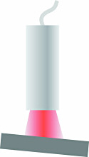 Figure 16. Lack of parallelism will introduce errors |
While probe materials are selected to minimize these environmental errors, in applications requiring utmost precision, control of temperature and humidity is standard practice. International standards specify that measurements shall be performed at 20°C or corrected to "true length" at 20°C.
Capacitive sensors provide stable, high-resolution measurements that can solve a myriad of measurement problems. Understanding their operation, terminology, and susceptibilities will make it easier for you to choose the right sensor and to use it successfully in your application.