
We exist in a world which has experienced rapid sensor proliferation; in fact, sensors are so commonplace now that we do not think twice as we each carry multiple different types with us daily in our mobile phones. These sensors provide the ability to detect simple changes in pressure, temperature, acceleration and gravity as well as more advanced sensors like GPS, RADAR, LIDAR and Image Sensors.
Sensor fusion is the extraction of data from several different sensors to generate information which cannot be provided from one sensor on its own. This information can then be further processed and analyzed and, depending upon the end application, it can be used to make decisions as necessary. When it comes to sensor fusion there are two classifications:
- Real Time Sensor Fusion – The sensor data is extracted and fused, with the decision based on the resulting information made in real time.
- Offline Sensor Fusion – In this approach the sensor data is extracted, fused and decisions are made at a later point in time.
When it comes to embedded vision systems and sensor fusion applications, most applications fall within the real-time classification.
Embedded Vision Applications
Embedded Vision applications are experiencing significant growth across a wide range of applications, from Robotics, Advanced Driver Assistance Systems to Augmented Reality. These Embedded Vision applications provide a significant contribution to the successful operation of the end application. Fusing the information provided by the Embedded Vision system with information from different sensors or multiple sensors further enables the environment to be understood, increasing performance for the chosen application.
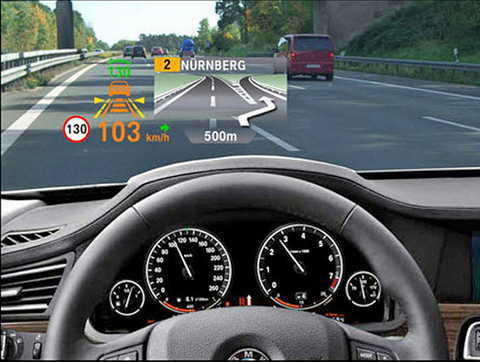
Many Embedded Vision applications use only a single image sensor to monitor one direction, for example looking forward from the front of an automobile. Using an imaging sensor like this provides the ability to detect, classify and track objects. However, the use of a single sensor means that we are unable to measure the distance to objects within the image. That is, we could detect and track visually another vehicle or pedestrian but would be unable to determine if there is a risk of collision or not without another sensor. In this example, we would need another sensor like RADAR or LIDAR, which has the ability to provide the distance to the detected object. As this approach fuses information from several different sensors types it is referred to as heterogeneous sensor fusion. In figure 1, information from multiple sensor types demonstrates Advanced Driver Assistance Systems (ADAS) heterogeneous sensor fusion.
An alternative approach would be to provide a second imaging sensor which would enable stereoscopic vision. This approach enables two image sensors facing the same direction yet separated by a small distance, akin to the human eyes, to determine the depth of objects in the field using parallax. When multiple image sensors of the same type are used, it is called homogeneous sensor fusion.
Of course, the application at hand will determine the driving requirements for the architecture used and the sensors types selected. These include the range over which depth perception is required, the accuracy of the measurement, ambient light and weather operating conditions, cost of implementation and the complexity of implementation.
It is, however, not just object detection and avoidance that Embedded Vision applications are used for; they may form part of a navigation system which uses an embedded vision system for traffic sign information. The fusion of several differing images, e.g. X Ray, MRI and CT for medical applications, or visible and Infra-Red images for a security and observation application, are a couple of further application examples.
While we often consider Embedded Vision, applications utilizing the visible electromagnetic spectrum, we must also remember many Embedded Vision applications fuse data from outside the visible electromagnetic spectrum.
Device Selection
Within embedded vision systems it is common to use All Programmable Zynq-7000 or Zynq UltraScale+ MPSoC devices to implement the image processing pipeline. If these make sense for traditional Embedded Vision applications, then they really stand out for Embedded Vision fusion applications. The tight combination of the processor system and programmable logic enable removal of bottlenecks, the reduced determinism and the increased latency which would arise in a traditional CPU/GPU based implementation. The flexible nature of programmable logic IO structures allows for any to any connectivity to high bandwidth interfaces such as image sensors, RADAR and LIDAR etc.
In figure 2, a traditional CPU/GPU approach is compared to an all-programmable Zynq-7000 / Zynq UltraScale+ MPSoC.
Examining an Embedded Vision sensor fusion application, we can further utilize the processor system to provide an interface to many lower bandwidth sensors. For instance, accelerometers, magnetometers, Gyroscopes and even GPS sensors are available with Serial Peripheral Interfaces (SPI) and Inter Integrated Circuit (I2C) interfaces, which are supported by both All Programmable Zynq SoC and Zynq UltraScale+ MPSoC devices. This enables the software to quickly and easily obtain the required information from a host of different sensor types and provide for a scalable architecture. What is needed is a way to develop the sensor fusion application using industry standard frameworks like OpenXV, OpenCV, and Caffe, this is where the reVISION stack comes in.
reVISION Stack
The reVISION stack enables developers to implement computer vision and machine learning techniques. This is possible using the same high level frameworks and libraries when targeting the Zynq-7000 and Zynq UltraScale+ MPSoC. To enable this, reVISION combines a wide range of resources enabling platform, application and algorithm development. As such, the stack is aligned into three distinct levels:
- Platform Development – This is the lowest level of the stack and is the one on which the remaining layers of the stack are built. This layer provides the platform definition for the SDSoC tool.
- Algorithm Development – The middle layer of the stack provides support implementing the algorithms required. This layer also provides support for acceleration of both image processing and machine learning inference engines into the programmable logic.
- Application Development – The highest layer of the stack provides support for industry standard frameworks. These allow for the development of the application which leverages the platform and algorithm development layers.
Both the algorithm and application levels of the stack are designed to support both a traditional image processing flow and a machine learning flow. Within the algorithm layer, there is support provided for the development of image processing algorithms using the OpenCV library. This includes the ability to accelerate into the programmable logic a significant number of OpenCV functions (including the OpenVX core subset). While supporting machine learning, the algorithm development layer provides several predefined hardware functions which can be placed within the programmable logic to implement a machine learning inference engine. These image processing algorithms and machine learning inference engines are then accessed, and used by the application development layer to create the final application and provide support for high level frameworks like OpenVX and Caffe. Figure 3 depicts how the reVISION stack provides all the necessary elements to implement the algorithms required for sensor fusion applications.
Architecture Examples
Developing the object detection and distance algorithm previously explained, a homogenous and heterogeneous approach can be demonstrated using the reVISION stack. This enables the sensor fusion algorithms to be implemented at a high level. Bottlenecks in the performance of the algorithm can then be identified and accelerated into the programmable logic.
To leverage the reVISION stack, we first need to create a platform definition which provides the interfacing and base programmable logic design to transfer the images and other sensor data into the processor system memory space. Implementing the homogenous object detection system requires that we use the same sensor types, in this case a CMOS imaging sensor. This has the benefit of enabling the development of only one image processing chain. This can be instantiated twice within the programmable logic fabric for both image sensors.
One of the driving criteria of the stereoscopic vision system, the homogeneous architecture requires the synchronization of both image sensors. Implementing the two image processing chains within the programmable logic fabric in parallel and using the same clock with appropriate constraints can help achieve this demanding requirement.
While the calculation of the parallax requires intensive processing, the ability to implement the same image processing chain twice results in a significant saving in development costs.
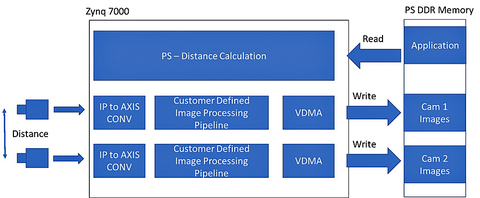
Figure 4 depicts homogeneous sensor fusion in an all-programmable FPGA.
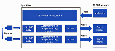
The architecture of the homogeneous approach shown above shows the two image processing chains, which are based predominantly upon available IP blocks. Image data is captured using a bespoke sensor interface IP module and converted from parallel format into streaming AXI. This allows for an easily extensible image processing chain; while we can transfer the results from the image processing chain into the processor system DDR using the high performance AXI interconnect combined with video DMA.
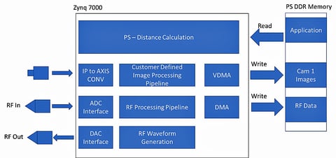
When we consider the heterogeneous example, which uses differing sensor types, we could combine the image sensor object detection architecture as outlined above with RADAR distance detection. With the implementation of the RADAR, we have two options: a pulsed approach (Doppler) or a continuous wave. The decision as to which will depend upon the requirements for the final application; however both will follow a similar approach.
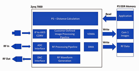
The architecture of the RADAR approach can be split into two: the signal generation and signal reception. The signal generation will generate the continuous wave signal or the pulse to be transmitted. Both approaches will require the signal generation IP module to interface with a high-speed digital to analogue convertor.
The signal reception again requires the use of high speed analog to digital convertor to capture the received continuous wave or pulsed signal. When it comes to signal processing, both approaches will utilize a FFT based analysis approach implemented with the programmable logic fabric; again, we can transfer the resultant data sets to the PS DDR using DMA.
Regardless of which implementation architecture we choose, once we have the sensor data accessible to the processor system and the reVISION platform created we can develop the sensor fusion system using the higher levels of the reVISION stack at the algorithm and application level.
At these higher levels, we can develop the application using a high-level language and using industry-standard frameworks.
For both embedded vision and machine learning applications reVISION provides acceleration-ready libraries and pre-defined macros to enable the acceleration of the application. This utilizes unused resources within the platform design, thanks to the SDSoC system optimizing compiler which combines High Level Synthesis with a connectivity framework.
Taking the heterogeneous example using two image sensors a standard development approach would be to create a stereo disparity map to determine the depth information. Commonly, this would be implemented using OpenCV function stereo block matching. reVISION provides an acceleration capable Stereo Block Matching function which is capable of being accelerated into the programmable logic. This function can combine two images to generate the disparity and depth information which forms the core of the heterogeneous example.
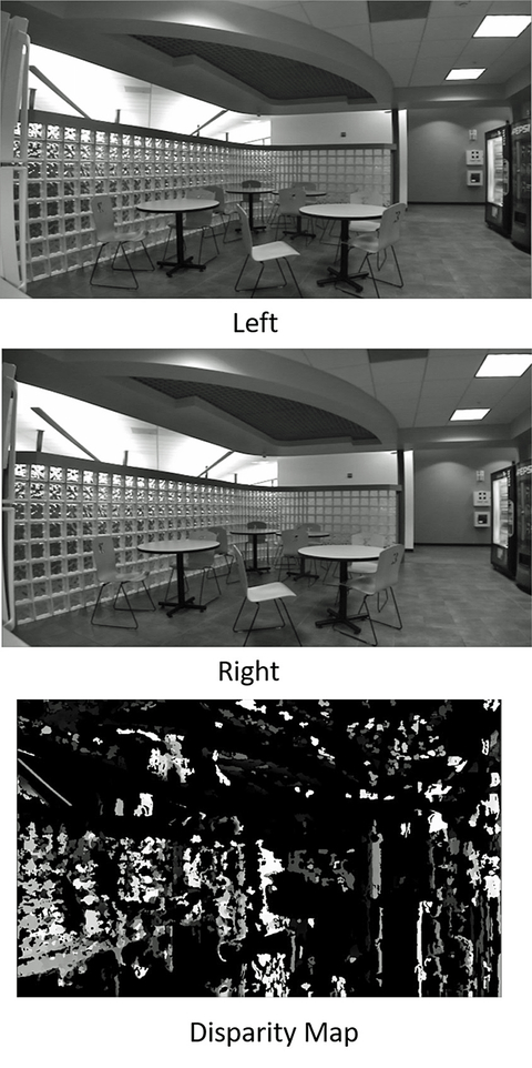
images on the left and center to generate a stereo disparity map on the right.
Conclusion
Sensor fusion is here to stay - there is a significant growth in embedded vision systems and rapid proliferation of sensors. The capability provided by reVISION to develop applications at the high level using industry standard frameworks enables a faster development of the sensor fusion once the basic platform has been developed.
About the authors
Nick Ni is the Sr. Product Manager of Embedded Vision and SDSoC. His responsibilities include product planning, business development and outbound marketing for Xilinx’s software defined development environment with focus on embedded vision applications. Ni earned a master’s degree in Computer Engineering from the University of Toronto and holds over 10 patents.
Adam Taylor is an expert in design and development of embedded systems and FPGA’s for several end applications. Throughout his career, Adam has used FPGA’s to implement a wide variety of solutions from RADAR to safety critical control systems, with interesting stops in image processing and cryptography along the way. Most recently he was the Chief Engineer of a Space Imaging company, being responsible for several game changing projects. Adam is the author of numerous articles on electronic design and FPGA design including over 200 blogs on how to use the Zynq for Xilinx. Adam is a Chartered Engineer and Fellow of the Institute of Engineering and Technology, he is also the owner of the engineering and consultancy company Adiuvo Engineering and Training.