
During an automated manufacturing process, the product typically moves along a production line at either constant or variable speeds. The first task of optoelectronic inspection is to discard that motion. For example, machine vision systems use triggers and shutters and photoelectric sensors use gates to freeze the object at a particular point in time so that it can be analyzed.
The Synchronizing Inspection Sensor
The synchronizing inspection sensor (SIS) is a new type of optoelectronic inspector that takes advantage of, rather than discarding, object motion to detect and inspect objects, and to synchronize the action of an actuator with their position. By using the multiple viewing perspectives afforded by object motion, the SIS provides capabilities beyond the reach of conventional optoelectronic inspection, without the need for triggers, gates, and careful arrangement of multiple detectors.
 The Ottakringer Brauerei AG in Vienna, Austria, is using the Cognex Checker 101, whose underlying technology is the synchronizing inspection sensor, to guarantee that beer crates and boxes of canned beverages contain the correct amount of product |
To obtain images from multiple perspectives, multiple frames are captured and analyzed as an object moves through the field of view. To obtain multiple views, it is desirable that the object moves no more than a few pixels between successive frames, which requires a sensor-processor combination capable of very high frame rates. Our SIS uses an inexpensive DSP and a CMOS imager that can capture and analyze images at 500 frames/s, far higher than the 30–60 frames/s provided by vision systems for the past 25 years.
The keys to high frame rate operation are a fast shutter, low pixel transfer time, and fast image processing. All lead naturally to low image resolution. With fewer pixels, each pixel can be made much larger and therefore more light sensitive, allowing fast shutters. With fewer pixels, transfer and processing time is clearly reduced. Our SIS's imager is only 128 x 100 pixels, about 20 x fewer than the typical vision system and about 12,000 x more than a photoelectric sensor.
Operating Principle
An SIS captures and analyzes frames continuously, overlappping each frame capture with analysis of the previous one. Our SIS achieves 500 frames/s operation with a 300 μs shutter.
The following analysis steps are performed for each frame:
1. Attempt to locate an object in the frame.
2. If an object was located in step 1, inspect the object for presence or absence of one or more features.
3. Considering the recent history of frames, decide whether there is sufficient evidence to conclude that an object has been detected.
If we conclude in step 3 that an object has been detected, additional analysis steps are performed:
4. Considering the same recent history of frames, decide whether there is sufficient evidence to conclude that the object has passed inspection.
5. Produce output pulses indicating that an object was detected, and whether or not it passed inspection. The pulses occur at a predefined synchronization time, corresponding to a precise location of the object along the production line, e.g., at the time when the object crosses a reject actuator.
Note that if inspection is not required, steps 2 and 4 are skipped.
Locating and Detecting Objects
Step 1 answers two questions:
- 1. How confident are we that an object appears in the current frame?
- 2. If we are sufficiently confident, where is it?
Our level of confidence is a numerical value called an object detection weight. We are sufficiently confident if the object detection weight exceeds some threshold. Frames for which we are sufficiently confident that an object has been located are called active frames.
Being sufficiently confident does not mean that we are right, however. Artifacts of viewing direction, illumination, manufacturing process, and object appearance may make it seem that an object is present when none is, or not present when one is. Unlike a vision system looking at one image, with an SIS these unavoidable errors of judgment usually do not lead to incorrect decisions, because those decisions are based on multiple viewing perspectives.
Our SIS uses gray-scale normalized correlation to locate objects. Normalized correlation is fast, robust, unaffected by image contrast, and easy for inexperienced operators to configure. An operator chooses a single correlation model at set-up time, which provides two degrees of freedom for object location and some tolerance for rotation. The object detection weight is simply the normalized correlation value.
For an SIS, where object motion is an integral part of the process, the two translation degrees of freedom in the image are called machine direction (the direction of motion), and cross direction (perpendicular to the direction of motion). A region within which to search for the correlation model must also be chosen. SIS simplifies the choice. In the cross direction, the operator chooses the search range based on the uncertainty of object position in that direction, as is usual for correlation methods. In the machine direction, however, the choice can be automated if the SIS has available a rough estimate of object speed.
Consider an example: Suppose the object is estimated to travel at 50 in./s, and the SIS field of view in the machine direction is ~3 in. With 128 pixels in the machine direction in this example, and 500 frames/s, the object motion is ~4.3 pixels/frame. Suppose we'd like to see the object about six times as it passes through the field of view. This gives a search range in the machine direction of ~26 pixels. Furthermore, since the object is moving in the machine direction, it doesn't really matter where in the field of view we look.
Note that this value is not critical. If the object moves twice as fast, we'll still see it three times; a vision system will see it only once. Furthermore, note that the search range in the machine direction is much smaller than the field of view. We don't have to look everywhere for the object—because of the motion, we can wait for it to come to us. This significantly reduces the search time.
Locating an object in the current frame (step 1) is not the same as detecting an object (step 3). Generally we want to see an object pass entirely through the machine direction search range with sufficient confidence, keeping in mind that judgment errors may affect individual frames. We are therefore looking for a set of approximately consecutive active frames, followed by some number of inactive frames. We decide that an object is detected when we see such a set that satisfies appropriate statistical tests, using data such as the number of active frames and the object detection weights.
We want a sufficient number of active frames so that isolated frames that may represent errors of judgment do not cause an incorrect detection decision, and so that sufficient inspection evidence and location data are obtained to make reliable inspection and synchronization decisions. What is sufficient depends somewhat on object speed. For rapidly moving objects we may get only two frames; for slowly moving objects we may want more. We also want to limit the number of active frames so that the detection decision does not take too long for slowly moving objects. If some appropriate limit of active frames is reached, a detection decision is made immediately.
Inspecting Objects
For each active frame, the SIS inspects an object by examining one or more sensor regions (SRs) in the current frame. Each SR is positioned based on the object location as determined in step 1, so that the SRs track the object as it passes through the field of view. Generally, each SR is configured to detect the presence or absence of an object feature—although, in general, criteria more sophisticated than presence/absence can be determined.
An analysis of each SR produces a measure of confidence that the object passes inspection for the current frame. This measure of confidence is a numeric value called an object pass score. A wide variety of techniques can be used for inspection, representing various tradeoffs among desirable attributes. Once again the paramount attributes for our SIS are speed and ease of configuring. We use three simple methods for analyzing an SR: brightness, contrast, and template match (using normalized correlation).
Inspecting an object in the current frame (step 2) is not the same as deciding whether the object passes inspection (step 4). When we decide that an object has been detected (step 3), we examine the statistics of the set of active frames to decide whether the object passes inspection. A variety of metrics can be used to make the decision; our favorite is a weighted average of the object pass scores, where the weights are the object detection weights. This favors those frames for which we are most confident that the object was indeed present in the field of view.
Synchronization
Two output signals are used to indicate that an object has been detected, and whether or not it passes inspection. The preferred arrangement is to produce a pulse on the first signal for object detection, and a pulse on the second signal for objects that fail inspection. For controlling a reject actuator, we can simply ignore the object detect pulse and wire the object reject pulse directly to the actuator.
These arrangements work only because the pulses are synchronized with the object's precise location in the manufacturing process. For example, when the object reject pulse is wired directly to a reject actuator, the pulse must arrive precisely when the object is at the actuator. The synchronizing repeatability that can be achieved with an SIS is one of its most remarkable attributes. We have measured repeatability in practical applications at better than 1/20 of the frame time—or <100 μs. Synchronizing repeatability arises from the high subpixel accuracy of the object location method and the use of multiple frames.
To understand synchronization, please refer to Figure 1 which shows objects moving along a conveyor past an SIS wired to a reject actuator. The actuator has just rejected a defective object, which was previously detected and inspected by the SIS. The output pulse to the actuator was timed to synchronize the action of the actuator with the position of the defective object.
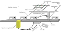 Figure 1. A demonstration of the principle of synchronization, in which objects move along a conveyor past a synchronizing inspection sensor wired to a reject actuator; the actuator has just rejected a defective object |
As can be seen in the figure, an object is present in the field of view for an amount of time that varies from object to object, depending on object speed, frame rate, the accidental timing of the object in relation to the frame times, and other factors. This variability is shown in the figure by the thick, fuzzy lines that bound this time period. Note that the active frames for each object fall within this time period.
During this time period, the object crosses a fixed, arbitrary reference point called the mark point. After the object has passed through the field of view, the SIS decides that an object has been detected and whether it passes inspection. This decision point occurs at a variable and unpredictable decision delay from the mark point. Any output pulse produced at the decision point would be useless for actuator control or any purpose that requires synchronization.
 |
At the decision point, the SIS has available the location of the object in the machine direction for every active frame, as well as the precise time at which the frame was captured. From these data, the precise time at which the object crossed the mark point (the mark time) can be calculated by linear regression. Keep in mind that it doesn't matter where the mark point is located, as long as it is fixed relative to the SIS field of view and therefore fixed relative to the manufacturing process.
Once the mark time is known, the output pulses can be delayed by a configurable synchronization delay relative to the mark time. If the production line is moving at constant speed, this delay corresponds to a precise downstream location of the object, the synchronization point.
For more flexibility, an encoder is connected to the SIS to track the motion of the production line. The image capture times, mark time, and synchronization delay can all be calculated just as easily using encoder counts instead of time. With such a setup, the production line need not be moving at constant speed for precise synchronization. Note that no pixel size calibration is needed for precise synchronization, whether using time or encoder counts.
With an encoder, the SIS can calculate for each object at both the actual speed in counts/s, and the apparent speed in pixels/s. This provides a precise pixel size calibration for each object. Furthermore, the relationship between apparent and actual speed is an indirect measure of the distance between the object and the SIS, a useful measurement that can be made at no additional cost.
Bill Silver, MS, can be reached at Cognex Corp., Natick, MA; 508-650-3000, [email protected], www.cognex.com.