

Introduction
Torque monitoring in drive train systems has historically been used as an effective means to predict system degradation, as well as maintenance intervals for existing mechanical systems. By routing requisite strain gauge bridge rosette wiring through a mechanical slip ring, and utilizing conductive brushes to transfer signal from one side of the slip ring to another, it is possible to convey electrical signals and power from a fixed frame to a rotating frame and hence, achieve a relatively complex measurement system for shaft torque monitoring.
Mechanical slip rings are historically complex; some exhibit unreliable characteristics; most are maintenance intensive, and all require hard wiring that takes many man-hours to install, add to flight system downtime, and add significant weight to the platform. A specific undesirable aspect is the signal output as transferred by a slip ring assembly is susceptible to induced noise generated by the resistance change of the brush.
Fig. 1: Traditional slip-ring concept drawing
Brush material will cause a disparity in transmitted voltage values as a result of its variable resistance. This variation is due to the conductivity of different materials in the brush-to-ring interface¹. Most commercial off the shelf slip ring products have an associated noise metric as part of their specification. Also, several Navy Bell H-1 main rotor gearboxes have been removed due to debris generated from slip ring bearing wear. A slip ring seizure is responsible for the loss of a Piasecki H-16 during flight test². For these reasons, many rotorcraft platforms forego strain/torque measurement at the main and tail rotors, choosing instead to monitor torque at the engine. Due to the highly coupled interaction between the main and tail-rotor and maneuver-dependent power requirements, estimation of main- and tail-rotor power is difficult for all maneuvers except a hover. Direct measurement of the main rotor/tail rotor ratio would yield significant advantages for investigations and event reconstructions. Non-contact systems have obvious advantages over mechanical slip rings in that many designs utilize components with no relative motion and do not interfere with the balance of the test component — a particular concern in high-speed applications. Several non-contact and/or wireless torque measuring devices exist using optical methods, in-line couplings and magnetic field measurement. While these technologies have merit for certain applications, many require a fixed reference frame in close proximity to the component under study to mount the corresponding receiver device, or use a custom (or significantly modified) shaft. In many aircraft installations, limited space is allocated for instrumentation; custom/modified parts carry airworthiness concerns, and airframe modification to accept mounting provisions often adds to the complexity of the test setup. Recently, LORD MicroStrain developed and tested a wireless torque monitoring system for use with industrial and military aerospace applications. Aptly named the Torque-Link, it is powered by dual 3V replaceable lithium ion primary cells, with an operating life of 40+ continuous hours, extendible to several months depending on application and usage mode. Although wireless sensor networks (WSN's) are gaining popularity within the aerospace and flight test communities, they are mostly used in a capacity independent of Health Usage and Monitoring systems (HUMS). Current HUMS systems use fixed line connections to sensors and data collection sources³. The initial LORD product, the Torque-Link LXRS® prototype, was designed for use on the MQ-8B "Fire Scout" VTUAV platform tail rotor drive shaft. U.S. Naval Air Systems Command (NAVAIR) requested LORD support to measure tail rotor driveshaft torque for the Fire Scout weaponization program after their previous slip ring instrumentation failed during a test flight. The substitute design by LORD was expected to replace the mechanical slip ring for ground test only. When firing rockets in proximity to the aircraft engine inlets, the hot rocket exhaust gas released can cause unwanted and unexpected responses in an engine's compressor stage. Previous testing had confirmed that rotorcraft are especially susceptible to significant tail rotor torsional responses during an Armament Gas Ingestion (AGI) event as the engine surges and recovers4. This torsional response may "ring" the driveshaft, causing damage to the tail rotor drive shaft and gearbox. Understanding the tail rotor driveshaft's torque response to this torsional impulse was necessary for NAVAIR to assess tail rotor drive system fatigue damage.
System Components
The LORD MicroStrain Torque-Link consisted of two half-shell assemblies that clamped down over the UAV's production tail rotor driveshaft. One half of the assembly supported the power source and requisite wiring; the other half supported the electronics sensor package and strain gauge rosette wiring. The system was held in place via clamping force of the two half shells onto the aluminum drive shaft, and all fasteners were safety wired, utilized nylon patch locking technology, or were installed with Loctite for retention. Steel Helicoils were installed in the housing attachment fastener holes for further fastener strength capability.
To satisfy NAVAIR airworthiness requirements, stress analysis was performed on the Torque-Link™ to ensure that the housing and fasteners would withstand the centrifugal loads at speed and expected torque during testing. A stress analysis was also performed on the driveshaft to account for bending stress associated with the weight and centrifugal loads during operation.
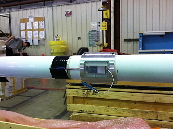
Fig. 2: Torque-Link and Strain Gauge Rosette Installed onto Tail Rotor Drive Shaft (temporary antenna attached for ops checks)
Specific inspection instructions were inserted into the flight clearance for ground testing to check for assembly retention on the shaft. Due to the unique, single-piece, configuration of the tail rotor driveshaft in this application, dynamic balancing of the unit on the shaft was considered too costly for this test.
The Torque-Link assembly balance was determined analytically to be well within the required dynamic balance for the application. Onboard instrumentation monitored the aircraft's tail rotor driveshaft vibration during testing. The Torque-Link employs a LORD MicroStrain SG-Link-OEM LXRS for sensor measurement. The sensor package transmits data wirelessly via IEEE 802.15.4 Protocol. Sensor data is received by a Wireless Sensor Data Aggregator (WSDA) unit. Depending on the configuration of the WSDA, it can operate in a user controlled manner or completely autonomously.
Fig. 3: WSDA-Base Wireless Network Architecture
For this application, it was used as a wireless base station controlled by a user with a laptop computer and LORD MicroStrain Node Commander software.
System Calibration
A static calibration stand setup was used to derive slope and offset coefficients for the wireless data. The test stand utilized the actual torque shaft from the UAV cradled in a support bed, which allowed a portion of the torque shaft to cantilever out freely by approximately 70". The Torque-Link and strain gauge rosette were installed on the shaft. The end of the torque shaft was fitted with a moment arm fixture as shown.
Masses were hung from the moment arms to obtain known torque values, which were then correlated to the wirelessly transmitted strain gauge values to obtain calibration coefficients. Measurements were collected utilizing a full strain gauge bridge that eliminated any bending loads and was compensated for temperature effects. The calibration scheme utilized test points for both positive and negative torques (user defined positive sign convention), and anticipated ground test and flight loads.
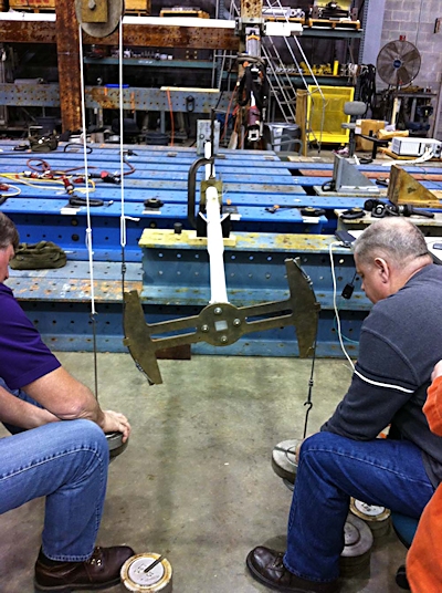
Fig. 4: FireScout Torque Shaft Electronics Calibration
The Torque-Link sampling rate was intentionally set high to ensure that the driveshaft's first torsional mode was captured. Due to cost and schedule constraints, a rotor-dynamic model of the tail rotor drive system was not created for this test. The shaft's torsional mode was determined to be higher frequency than the tail rotor drive system's mode due to the added tail rotor gearbox and loaded tail rotor system inertias.
System Setup
The Torque-Link system was installed on the tail rotor drive shaft. It was placed in a manner as to not interfere with UAV empennage structure, and located adjacent to aft structure access panels for the sake of wireless signal propagation. The nature of the internal aircraft structure lends itself poorly to facilitating RF communication, instead causing multipath issues that degrade wireless signal strength³. In this case the access panel could be removed for ground testing if RF propagation proved to be inadequate.
Error! Reference source not found. Shows the wireless torque monitoring node installation accomplished on the NAVAIR flight test vehicle as viewed through the left side empennage access panel.
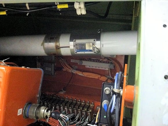
Fig. 5: MQ-8B FireScout Torque-Link Installation
Ground Test
The MQ-8B weapons program consisted of several distinct tests. The ground test was chosen as risk reduction for eventual inflight testing. The ultimate goals of the ground testing were to A) determine whether the aircraft was affected by AGI and B) measure the resulting torque impulse on the tail rotor drive shaft. The UAV was attached to a ground test stand at Patuxent River Naval Air Station. The Torque-Link was configured to datalog for the window of measurement, which was approximately 3 minutes in duration. Data was collected at 2048 samples per second with an onboard 500-Hz anti-aliasing filter, and stored in node memory. At the conclusion of the data collection window, measurement data was transmitted wirelessly to a base station.
The ground testing culminated with a total of six test points where wireless torque data was successfully collected from the tail rotor drive shaft during operation and while firing ordnance. An example of the collected data with an averaging filter applied is shown in Figure 6 - Error! Reference source not found, and revealed that there was no significant torsional impulse in the collected data.
Figure 6: MQ-8B Ground Test Data, Rocket Fire Event, Port Side; red is actual data, blue is averaged data.
A typical torque profile demonstrating startup, ground idle, and flight power captured by the Torque-Link is shown in Figure 7 is comparable to that collected with the slip ring prior to its failure, and data collected during previous flight tests.
Fig. 7: Measured Tail Rotor Torque Profile for MQ-8B; Engine Startup, Ground Idle, Flight Power; red is actual data, blue is averaged data.
Due to the transient nature of the firing impulse, the FFT data was plotted with time, in a waterfall plot, to show the system's response in the frequency domain at discrete points around the firing event. The FFT is shown in Figure 8.
Fig. 8: MQ-8B Ground Test Data, Rocket Fire Event, FFT Waterfall Plot (Event occurs at 45.5 seconds along Z axis)
Flight Test
Despite the initial development concept of ground test only, NAVAIR was satisfied with the design and performance of the hardware and proceeded to utilize the Torque-Link system for in-flight data collection on the MQ-8B. Several potential methods for data collection were discussed. For truly autonomous data collection, the wireless network could use a WSDA-RGD for GPS timing, network synchronization, wireless data collection, and data storage.
Another option is to fly a second aircraft in parallel with the flight test vehicle. This "chase" aircraft would have an operator with a LORD MicroStrain base station and laptop. From a relatively short distance away from the flight test vehicle, the operator can pass commands to the wireless node for data collection, data download, and wake / sleep operations.
A third option would be to "arm" the wireless node for data collection on the ground, fly the test points while collecting data, and wirelessly download the data from the node when the air vehicle returns. This method has time limitations based on the internal memory of the wireless node, and the data sample rate selected by the user, but given the sub-second transient nature of the test event, the memory limitation was considered an acceptable compromise.
The LORDNAVAIR Public Release 2014-53 Distribution Statement A - Approved for public release; distribution is unlimited MicroStrain base station antenna was able to wake the Torque-Link™ node and collect data from the chase aircraft within roughly 20 feet. NAVAIR has completed its in-flight weapons testing for the MQ-8B and the Torque-Link LXRS system provided valuable tail rotor torque data while minimizing impact to the vehicle's weight and balance and shaft dynamic balance.
Conclusions
Data collected using the LORD MicroStrain Torque-Link LXRS successfully met its objective to provide tail rotor torque data during the ground test portion of the MQ-8B weapons program AGI test. The Torque-Link™ further provided data during in flight testing that allowed NAVAIR engineering to make decisions to continue testing while ensuring the safety of the aircraft. Data analysis using Torque-Link collected data revealed that no transient loading occurred during the rocket fire/AGI window of observation. Likewise, no vibrational transients were detected with onboard aircraft health monitoring and feedback instrumentation during the same window of time.
Prior mechanical slip ring data also correlated with the data collected wirelessly. While it is beneficial to hypothesize that a dynamic event will occur, and then witness that event, in this case we did not detect a transient vibrational event. We conclude therefore, that a rocket fire and gas ingestion event that falls within these test criteria and conditions, do not induce a torsional loading transient on the tail rotor drive system for this rotorcraft.
The Torque-Link design is compact and light, minimizing impact to the airframe and driveshaft. Other instrumentation onboard the MQ-8B test aircraft confirmed that the Torque-Link did not affect the shaft's balance, which was considered a significant concern in this application.
LORD MicroStrain's technology allows engineers to instrument an aircraft without the need for wire bundles or mounting provisions. The scalability of LORD MicroStrain's wireless system also allows for simultaneous time synchronized strain, vibration, temperature and corrosion measurements at locations that may be difficult to capture using traditional wired means.
The wireless technology demonstrated in this project provides users with a low cost, quick turnaround alternative to conventional instrumentation and measurement techniques. Significant risk reduction in system complexity is apparent since, in this case, the user replaced a failed slip ring installation for their data collection, reduced aircraft instrumentation weight, and mitigated balancing concerns.
References
1. "Materials Application Guide: Slip Ring Material Application Recommendations".
2. "Piasecki PV-15 Transporter/YH-16".
3. Ketcham, R., Herbst, J., Phan, N., "Integration of a Wireless Sensor Data Aggregation System and HUMS," American Helicopter Society 69th Annual Forum, Phoenix, Arizona, 2013.
4. Clark, G., Chesser, A. "AH-1Z Rocket Gas Ingestion: Expanding the Envelope with Minimum Resources."
About the Authors
Chad Hodgkins graduated from the University of Florida with a B.S. in Mechanical Engineering and a B.S. in Aerospace Engineering in 2008. He has worked for NAVAIR at Patuxent River, MD since 2008 as a drive system engineer for several rotorcraft UAVs and a manned fixed-wing aircraft. In this capacity, he supports programs in all stages of development, from early acquisition to sustainment, and has been the lead test engineer on several drive system tests.
Dan O'Neil is a graduate of Norwich University (mechanical engineering). He has worked as an Air Force aircraft structural repair engineer, flight test engineer, and development engineer. He currently works for LORD Sensing Systems in Williston, Vermont as a Senior Mechanical Engineer developing wireless solutions for aeronautical and industrial customers.
Chris Townsend is a graduate of the University of Vermont and went on to work with MicroStrain, Inc. during its infancy. Since then, he has worked to develop new and dynamic wireless products, with a focus on Smart Sensing Systems. Townsend has since worked as the Executive VP of Engineering, and then as Senior Manager of Embedded Systems. Chris now works as a Business Manager for LORD Industrial and Wireless products.
Related Stories
Accurate Measurements of Vital Performance Issues, Built to Fit Your Application
Accurate Contactless Position Sensors Improve Performance, Reduce Cost of Electric Motors
Load Cell Amp Gives Robot Six Legs Up