

Artificial lift is a process that allows gas producers to optimize well production while minimizing overall maintenance and life cycle costs. When a gas well produces excessive volumes of fluid, the pressure of the natural gas in the well is unable to overcome the weight of the fluid trapped inside the tubing. The well is then unable to produce the natural gas because, essentially, it is blocked by the fluids. Plunger lift control is a form of artificial lift used by natural gas producers who experience heavy downhole fluid loads.
In instances where a well has been blocked by fluids, the common practice has been to manually shut in the well thus creating downhole pressure. The objective is to build enough downhole pressure to lift, i.e., enable extraction of the natural gas. To improve this process, producers also use a plunger to assist with lifting the fluid.
Technologies that combine artificial lift for plunger control and remote monitoring are keys to overall productivity and success. If there were enough technicians affordably available, remote monitoring would be less important. However, that scenario is not realistic.
By remotely monitoring a few critical data points, such as pressure, time, production volume, and line pressure, an operator can achieve maximum results at minimal cost and minimum risk for damage (Figure 1).
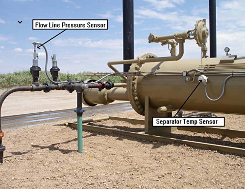 Figure 1. Sensors that can be monitored remotely |
The first two data points include both tubing and casing pressure. Understanding these respective pressures and how they correlate with one another allows an operator to determine fluid load. Once fluid load is determined, it is time to produce the natural gas. However, drawing out natural gas from the well too quickly can damage equipment and reduce daily revenues. Traditionally, this process was managed manually, with operators deployed to the well location to monitor plunger arrival times while simultaneously monitoring production volumes and thus understanding the dynamic production characteristics of that particular well. The operator then developed a time-based program using a mechanical timer that would shut in the well to accumulate enough downhole pressure to subsequently produce the natural gas.
The problem with this approach is that wells change with time and use. What might have been the right formula on a new well may not be adequate for a one-year-old well. It is even less likely that the program will remain correct over time since the production declines as the well ages.
The static nature and subsequent limitations of the mechanical timer lead to the desire for a self-optimizing plunger application. The most desirable is a field-based, well site computer that can monitor flow rates and adjust the time cycle to increase production as the well characteristics change.
Automation electronics manufacturers have been focusing much of their development effort on the plunger lift control application in recent years. They have created a series of algorithms that allow their electronics to self-optimize the plunger lift process. In other words, the controller or electronic flowmeter (EFM) learns and adapts to the changes in the well pressure. The algorithms use a collection of data points that include plunger arrival times (time), fluid load (tubing and casing pressure), and after flow (volume and time) to make decisions. Based on these data points, along with high/low thresholds set by an operator, the remote terminal unit (RTU), programmable logic controller (PLC), or EFM can automatically self-adjust and determine when to open the production valve, when to close the production valve, and how to optimize the overall process for lifting heavy fluid loads while achieving each respective well's maximum production efficiency.
This all contributes to the overall economics of a well during its life cycle. However, don't ignore the careful selection of equipment up front. Be sure to consider the up-front costs associated with the acquisition and deployment of plunger lift control technology, including the estimated lifecycles of the equipment. These include:
- Host software
- RTU/PLC/EFM
- Instruments
- Pressure sensors
- Switch devices
- Automated valves
- Analyzers
- Remote Communications
- RTU/PLC level
- Local
- Backhaul
- Remote Power—Solar Applications
- Solar panel
- Batteries
- Communication Equipment
- Suitability for the application
- Proper certifications
- Power consumption
- Customer support history
- Generational compatibility
- Installation
- Labor
- Equipment (Does not include plunger equipment)
- Time
- Materials
- Cable
- Conduit
- Fittings
- Valves
- Etc.
The cost of a plunger lift control automation package (installed) can run from $3,500 to $12,000. If that sounds expensive, consider the increase in well productivity that plunger lift control can deliver. Many documented cases from differing wells in different geographic areas suggest that a 12%–35% increase in production is attainable as a result of implementing automated plunger lift control systems on wells that produce high volumes of fluid.
Many operators are switching to new automated plunger systems. This monitoring and control functionality can be accomplished by hardwiring the instruments at the well head back to a control box, typically an EFM, or by deploying a new wireless radio technology know as Wireless IO (Figure 2). There are several radio and instrumentation manufacturers that offer Wireless IO at different levels of functionality, RF reliability, price, and other variables.
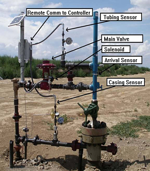 Figure 2. Wireless IO deployed on a well head |
What Is Wireless IO?
Wireless IO is a mechanism by which analog signals (1–5 V or 4–20 mA), such as those produced by temperature and pressure sensors, as well as discrete inputs (digital signals) produced for valve control, high-level tank alarms, and pulse counting, or other raw signals may be transmitted via radio to or from a central processing device (EFM, RTU, PLC) and to or from the sensor. On a plunger lift well these transmitted data would include level, flow, pressure, temperature, plunger arrival, alarms, and signals generated to control devices such as valves.
Why do this wirelessly? There are several compelling reasons:
- Fast installations—Wireless IO can be up and running in 30 min. versus the several days required for conventional wired methods.
- Low cost—On a single well site the cost of wireless can be lower than $2,000 to provide complete monitoring and control for a plunger lift automation.
- Minimal repairs required—A common source of irritation at well sites is the cut wire that was inadvertently severed when something was added later.
- No trenching required—Trenching is slow, time-consuming, and expensive with costs of $20/ft. common in many areas.
- No conduit required—Installing conduit is slow and expensive, with costs running $20/ft.
- Redeployable—Wireless is transportable. If the tank moves, take the radio with it. Even if the tank does not move, when the well is no longer producing, the wireless equipment can be just as easily de-installed as it was installed. It then can be installed in a new location.
Wireless systems save time and money on single well-pad installations, but in recent years many operators have switched to "pad" wells—multiple wells on one pad—reducing the overall footprint of the wells and allowing operators to share production facilities among multiple wells, reducing the facility's cost per well head, and lowering the lifting costs per MCF of gas, or barrel of oil produced (Figure 3). On the wireless control systems, instead of installing an RTU, EFM, or PLC at each well head you can use one RTU, EFM, or PLC per pad. These RTUs or EFMs are capable of collecting custody transfer information from multiple wells and also providing plunger lift control on all of the wells.
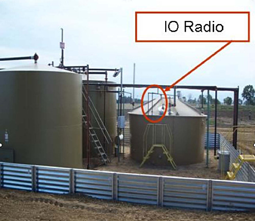 Figure 3. Multiple tanks on one radio |
At the well head, the operators use a stand-alone radio to read and transmit the casing pressure, tubing pressure, to determine the plunger status, and to control the valve. The radio does not provide any logic or decision-making capability, it acts only as a replacement for a wire between the EFM and the well head. The radio is constantly updating the EFM with well head information. Different manufactures use different update rates, but it is not uncommon to have information updates as often as six times per second.
Case studies have shown that the cost savings is $3,000 to $5,000 per well head to install a radio instead of an EFM. Consider that the savings on a directional drilling pad well could be $45,000 per pad based on a savings of $3,000 per unit and 15 units. Of course, one EFM unit is still required.
In the Rocky Mountain area of the U.S., pad wells are becoming the norm. Major producers in Colorado, Montana, Utah, New Mexico, and Wyoming are standardizing on wireless automation of their well heads. Many operators are including tank monitoring, flow rates, water meter monitoring, sump or pit monitoring, and flare monitors as well as chemical injection monitoring in the types of data that need to be collected wirelessly.
Important Wireless IO Features
Many new wireless radios have Modbus capability so they can theoretically bring thousands of data points back to the EFM or controller. Because of customer interest, many manufacturers now offer expandable IO radios, supplied with a base set of inputs and outputs and some of which give the option to add modules to expand the IO count. Wireless IO also offers operators the ability to extend the distance they can bring signals from remote equipment into a central point (Figure 4).
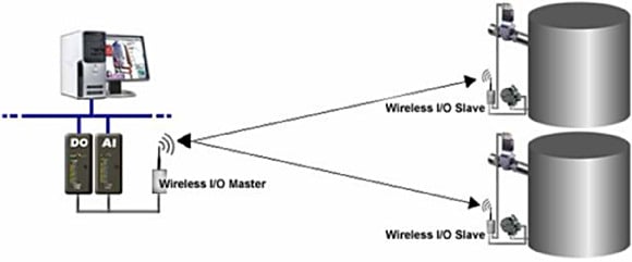 Figure 4. Wireless communication of tank levels |
Many Wireless IO radios can transmit data >30 miles with good line-of-sight (LOS) communication paths. Some offer a range of up to 60 miles for a clear LOS and perfect conditions but those conditions are difficult to achieve. However, such a radio is more likely to achieve reliable communications over shorter distances when obstacles are introduced than are shorter-range spec radios.
Another important selection criteria for a wireless IO device is whether it has a fail safe or default settings configuration. In the event of a communication loss, a device with fail safe will put the well into a predetermined configuration. No device is immune to a loss of signal (not even hardwired ones), and it is important that the radio be able to support the fail-safe conditions and make the changes to the situation as required. For example, if a wireless IO device that is monitoring tank levels loses its signal to the host (RTU), the user (you) should be able to choose what the fail safe condition will be. You can choose to have the valve close on loss of signal, thus preventing the possibility of overflowing a tank and having an EPA clean up (Figure 5). Alternatively, the valve can be set to go to open on loss of signal when spills are not an issue, or to do nothing until communication is restored.
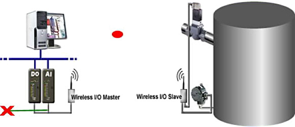 Figure 5. In the event of a communication failure, the I/O slave will control outputs based on the pre-programmed fail-safe default. |
A time delay is the ability to select how long the radio will wait, after the loss of signal, before taking any action. Should the radio change the valve status instantly on signal loss, or should it wait five minutes before taking action? Ideally, this should be user-selectable. Some manufacturers can provide a digital output from the radio to the EFM and create an alarm for loss of signal that will then be delivered to the software host and can be converted to a call out or can page the operator for notification of the loss.
A wired system may or may not provide these sorts of decision-support capabilities. Not all wireless systems provide this capability either. It is important, then, as a part of the wireless selection system, that the decision-support capabilities be an important, careful part of the evaluation.
Wireless Adoption
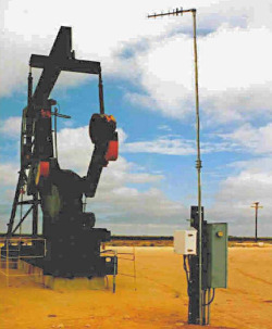 Figure 6. Wireless monitoring has proven its reliability in the oil and gas industry. |
Twenty years ago chart recorders, manual tank measurement with tape measures, and hand set timer clocks, were the normal tools of the trade for oil and gas production operations. In 2008, nearly 100,000 new wells in the U.S. and Canada were automated with electronic controls. The pace of change has increased every year, with electronics having overtaken manual devices by a 10:1 margin last year.
Technologies such as wireless IO save money, reduce labor costs, and improve efficiencies. The old adage about change is, "The decision to change only happens when the pain of change is less than the pain of staying the same." For most operators, that threshold has been crossed with wireless technology. Now the decisions have to be made on how to manage the pain of change and to minimize that pain. Here are a few suggestions:
Never trust but verify. New products claims sometimes have been exaggerated; a two-part evaluation of new equipment is prudent. First, ask the companies' representatives to bench-test the equipment in your facility. They should be able to validate that it will operate as advertised on the bench in your facilities. Second, ask for a field test. One of the important differentiating factors among manufacturers of wireless equipment is how well does it work in the real-world. The factors to consider in real world tests are:
- What is the range? How far can the radio reliably carry an accurate signal?
- Will the signal penetrate trees and foliage?
- How accurate are the readings when compared to the instrument that generates the signal (resolution)?
- How does the radio technology handle other radio traffic in the area? Some products fail when deployed in proximity to other radio signals.
- What is the power consumption of the radio? Some products are designed for in-plant operations and require significantly larger and more expensive batteries and solar panels to properly operate and extend the periods of power autonomy.
Take the time to do a little research and product validation. Taking time to talk to other industry experts such as your EFM manufacturer or local service provider, to see what their experiences have been with various products may save you time in getting to a small group of products you want to test before making your final decision. Ask about the service history of the product and the provider. Make sure that the service and support histories are consistent with the advertising and, especially, with your tolerance level for service calls.
If you have several wells for which you would like to try going wireless, ask those manufacturers on your short list to provide you with a pilot installation to allow you to compare apples to apples. Do not consider any manufacturer who is not willing to do head-to-head comparisons with its competitors.
Positive Change
One thing is certain. The world is changing and we are all adapting to keep up with those changes. Hopefully, you will find a group of vendors that share your excitement in making those changes. Having good partners will make it easier for everyone in your organization to make the transition. No one likes to change from the comfortable to the uncertain. Having experienced suppliers that help you and your staff make the leap of faith into new technology is very important.
ABOUT THE AUTHOR
James Gardner, BA Univ. of Washington, Oil & Gas Sales Manager, can be reached at FreeWave Technologies Inc., Boulder, CO; 866-923-6168, [email protected].