A differential pressure sensor is a special type of pressure sensor that measures the change in pressure or "DP" across two ports on a device. This is different from a static or absolute pressure sensor that would measure pressure using just one port. A barometer or altimeter is the classic example of an absolute pressure sensor, whereas an airspeed sensor is the classic example of a differential pressure "DP" measurement. "DP" is also a measure of flow, and hence many applications describe their requirement as a flow measurement.
Differential Pressure measurement for low-pressure ranges is required in Medical, Industrial, and Internet-of-Things applications. DP is measured in units of Pascals or Inches of Water Column. 1.0 Pascal (Pa) = 0.00402 inH20
A high-accuracy differential pressure measurement is one that achieves an accuracy better than 0.1 Pascal. Where might such a precise measurement practically be required? Here are a few examples:
- Continuous positive airway pressure (CPAP) is commonly prescribed to treat sleep apnea. The machines need a differential pressure sensor to regulate flow to the user. Recently machines have even started to report statistics on when a user has an “event” which is basically a period of high resistance to flow. The Apnea-Hypopnea Index (AHI) is used to quantify sleep apnea severity.
- Industrial applications such as zone control or measurement of room pressurization require reliable detection of small pressure changes, and the ability to filter out spurious pressure changes from occupant movement. Traditional gas residential and commercial metering applications.
- The “Internet of Things” has created a new class of smart-consumer device for air-quality and air-flow measurement needing high precision. These devices combine particle counters with air-flow measurement to measure the quantity of tiny PM2.5 particles in the air. Large quantities of PM2.5 particles have been shown to even cause mental illness in kids as well as other serious health ailments, so detecting such pollution affordable is likely a trend that will only grow.
These example applications and many more would like an accurate differential pressure sensor that can achieve this high-accuracy at low-cost. Lower cost can both increase a device manufacturers bottom line, and it also increases the affordability of end products. The best way to get low-cost and high-reliability is to utilize a technology that has already scaled to extremely large volume and low production costs. Aceinna's differential pressure family does just that.
Aceinna’s digital differential pressure sensor leverages a proven proprietary MEMS sensor element which has already surpassed a billion units produced. The new differential pressure sensor, the MDP200, has ±500 Pascal full scale range and can detect changes down to 0.02 Pascal or a tiny 0.00008 inches of water column!
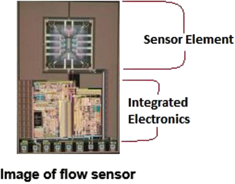
A sketch of the MEMS flow sensor device is shown in Figure 1. It uses the temperature differential created by a heated airflow to accurately detect the DP. The sensor is fully integrated with a custom I2C interface and produced with an automated calibration process that tests and calibrates each device at over 300 pressure points.

A micromechanical MEMS flow sensor can be made with one or more heaters and one or more temperature sensors. One simple way is to have one heater surrounded by two temperature sensors placed symmetrically at the left and right side of the heater. When the heater (a resistor) is heated by passing a current, a steady state temperature profile is build up around the heater. With the symmetry, the two temperature sensors sense the same temperature when the gas (media) is not flowing.
When the gas is flowing, for example, from left to right, the hot air is blown from left to right and thus the temperature sensor sees higher temperature than the temperature sensor at the left side. Since the temperature difference is proportional to the flow rate (linear at low flow rate and non-linear at high flow rate), we can determine the flow rate by measuring the temperature difference of the two temperature sensors

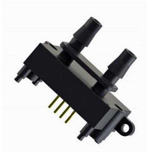
It is available in both a manifold and barb fitted package. Get the spec here.
In MDP200, the sensor is built with standard CMOS process. The MEMS sensor and the signal conditioning circuit is built together monolithically on a single chip by utilizing standard materials in the CMOS process to build the MEMS flow sensor.
In the CMOS process, the polysilicon and aluminum are readily available used for interconnects. We can use polysilicon as the heater resistor and the polysilicon and aluminum contact as the thermal couple as the temperature sensor. In such elegant approach, MEMS flow sensors can be built without needing any special materials and processes and the signal conditioning circuits can be naturally integrated with the sensor on a single chip.

chip enables smaller size, lower cost, much higher precision and control of the sensor.
By using an integrated CMOS circuit, one can sense the temperature difference down to micro-Kelvin - allowing very high resolution and low flow rate sensing. While a thermal flow measurement is both accurate and cost effective, there are other techniques for flow measurement. At the high-end of the flow market are sophisticated optical and sonar sensors. Optical flow sensors measure the flow rate by detecting particles and features in the flow stream and tracking the speed of those.
In contrast, sonar sensors are used when the sensor can't be placed in the flow stream. Sonar systems literally image the flow from outside the pipe. While both optical and sonar sensors have some advantages, they are generally far too expensive for high-volume low-cost applications such as consumer or industrial OEM devices, and they are reserved for scientific and instrumentation applications.
At the low end of the market, flow can be measured by using simple mechanical devices. For example, most residential gas flow meters still use a mechanical wheel or turbine placed in the gas flow. The spin rate of the wheel is counted using a magnetic sensor or other conventional means.
However, a solid-state MEMS sensor approach can provide both a significant cost and reliability benefit. Aceinna's MDP200 is in early trials for residential gas measurement. Since the theoretical limit of the sensing accuracy of a MEMS flow sensor is one million times better than a mechanical sensor, by the nature of the technology, any MEMS flow sensor is far better than mechanical ones.
Engineers developing products that rely on flow sensing need to be aware of the diverse spectrum of options and technologies that are available for their designs – from simple mechanical wheels to optical and sonar sensors, to the next generation differential pressure sensors based upon emerging thermal MEMS technologies that effectively compete with higher levels of accuracy as well as lower costs.

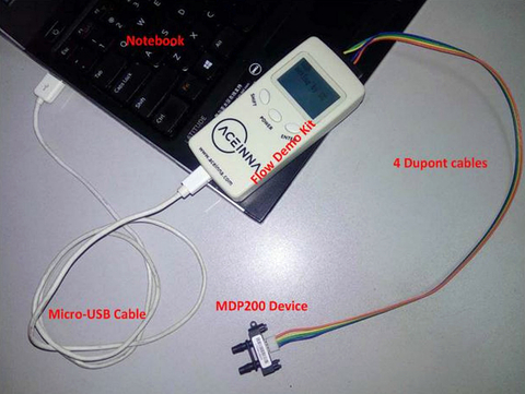
To make it easy to get started with MEMS DP and flow measurement, Aceinna offers a ready to go developers kit featuring a simple example readout circuit and LCD display, as well as digital USB interface and graphical user interface software for logging data. More info at https://www.aceinna.com.
About the author
Mike Horton is the CTO of Aceinna where he is responsible for corporate technology strategy and inertial-navigation related technology development. Prior to Aceinna, Mike Horton founded Crossbow Technology, a leader in MEMS-based inertial navigation systems and wireless sensor networks, with his advisor the late Dr. Richard Newton while at UC Berkeley. Crossbow Technology grew to $23M in revenue prior to being sold in two transactions (Moog, Inc and MEMSIC) totaling $50M. In addition to his role at Aceinna, Mike is active as an angel investor with two Silicon Valley based angel groups - Band of Angels and Sand Hill Angels. He also actively mentors young entrepreneurs in the UC Berkeley research community. Mike holds over 15 patents and holds a BSEE and MSEE from UC Berkeley.