Virtually all rotating and reciprocating mechanisms generate a vibration ‘signature’ that, when all is well with that mechanism, is representative of normal functioning. Excursions from that signature might indicate all manner of things: load changes, variations in speed and acceleration; however, an excursion could also reveal the early stages of a developing mechanical fault. But before such analysis can be undertaken, it is important to consider the vibration sensor itself – and, more particularly, its location and the way it is installed on the machine.

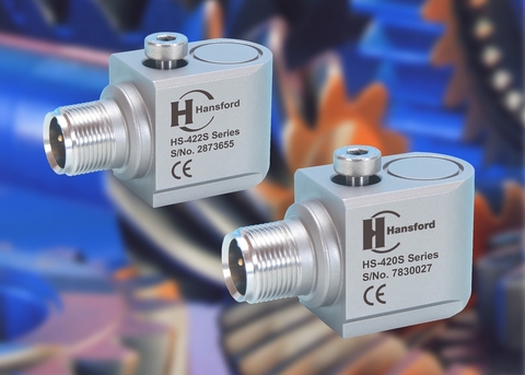
The growing trend among manufacturers to implement machine health monitoring systems throughout their plants and factories has seen a corresponding growth in the need for sophisticated vibration sensors. The designers of such sensors have not been slow in reacting to these demands. Today’s devices don’t just deliver exceptional performance and reliability; they are also packaged in a variety of resilient and compact enclosures that can cope with the rigors of tough industrial environments.
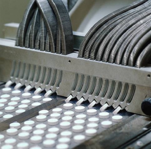
Vibration sensors are widely used in pharmaceutical manufacturing and have been for some time. However, there is evidence to suggest that the sector is not using vibration monitoring to its full extent, limiting the collection and analysis of important machine health data. Failure to analyze data correctly might partly be to blame for this, but often the reason is not getting the basics right – the fundamentals of locating and installing the vibration sensor in order to gain the full potential of vibration signature analysis. While a vibration sensor may offer high levels of performance and reliability, realizing these attributes in service will ultimately depend upon the skill of the installer.
There are two main categories of accelerometer: AC accelerometers, which are typically used with data collectors for monitoring the condition of high value assets, and 4-20mA accelerometers, which are commonly used in conjunction with PLCs to measure lower value assets such as motors, fans and pumps. Both AC and 4-20mA accelerometers can identify shaft misalignment, bearing condition and imbalance, while AC versions are also able to detect gear defects, belt problems, looseness and cavitation.

Installation
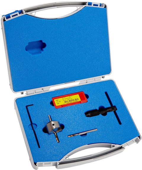
The accelerometer should be positioned as closely as possible to the source of vibration. If conditions (and product warranties) allow, the preferred mounting technique is to drill and tap a thread directly into the machine frame so that an accelerometer with an integral ¼-28UNF, M6 or M8 mounting thread can be screwed into place. This ‘drill and tap’ method can also be used to fix a mounting stud, to which an accelerometer can be attached; sensor manufacturers provide installation kits for this purpose.
A good spot facing kit will provide all the tools needed for accurate mounting, including a tapping drill, taps, tap wrench and a spot facing tool. A spot facing kit will also provide a flat mounting surface if the machine frame is not itself flat. When the sensor is finally screwed into place it is important to get the torque right. Over-tightening can damage the sensor by stripping the thread, while under-tightening will lead to inaccurate readings due to poor coupling with the vibrating surface.

If drilling and tapping is not an option, mounting studs can be adhesive bonded to the machine frame. The operating temperature of the application will dictate the type of adhesive used. Once installed, it is important to ensure that the accelerometer cable is clamped to the body of the accelerometer itself with cable ties. Apart from preventing cable damage, this also avoids false readings arising from the movement of loose cables.
Air handling: vibration monitoring in action
Effective air handling in the pharmaceutical sector requires machinery that can stabilize air conditions within precise limits during the manufacturing process, with no sudden changes to air flow rate, temperature or humidity. To ensure that the levels of these parameters are appropriately controlled, mechanisms within the air handling system must be monitored and carefully maintained.

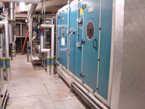
A typical air handling unit comprises a supply fan and an extractor fan, coils that circulate steam or hot water for heating, chilled water for cooling and air filters, encased within a large metal enclosure with removable panels. The complete fan and motor assembly is contained within the enclosure, the panels enabling easy access for maintenance. The supply fan and extractor fan can either be direct-drive or non-direct-drive. Direct-drive fans may require a vibration sensor on both the drive-end and non-drive-end bearing, while non-direct-drive fans may require the addition of two accelerometers on the journal bearings of the gear shaft.
An established and cost-effective technique for identifying imbalance and misalignment in air handling units employs 4-20mA sensors mounted on the bearing housings. In ‘online’ mode, the velocity readings are transmitted to a PLC, allowing vibration measurement in real-time and trends to be monitored. A dual output sensor can provide both a 4-20mA output and an AC output, allowing engineers to take in-depth vibration analyses via a data collector.
A further ‘offline’ option is to use fixed AC sensors hard-wired to switch boxes outside the air handling unit, allowing data to be collected safely from the same positions on a regular basis. The limitation of this option is that readings only apply to the moment in time that they were taken. If there is limited access, for example, near the belt guards, it is worth considering that side entry sensors and compact small footprint sensors can be used for small air handling units.
If all of these specification and installation issues are met, not only will the air handling unit be able to maintain air control consistently to the benefit of the plant as a whole, but it may also be possible to extend the operating life of equipment beyond recommended maintenance intervals – guarding against the cost implications of machine failure, downtime and unwelcome reductions in production volume or quality.
About the author
Chris Hansford is the Managing Director of Hansford Sensors Ltd. He is a qualified Electro-Mechanical Engineer and has over 35 years experience in vibration and condition monitoring. At the start of his career, Chris was employed as a Design Engineer by a company that provided condition monitoring services to the power sector.