
Mixed-signal submicron CMOS technologies permit high-performance system-on-chip designs with integrated sensors—such as photodiodes or Hall elements—to provide position sensing. The interpolation of analog sine signals has become a standard feature of the technology, enabling linear displacement measurement systems to achieve resolutions of <1 µm. If you repeatedly apply the procedure at staggered intervals, you can increase the accuracy of the reading.
The basis of this approach is the nonius principle, which uses Vernier scales in integrated designs. Whether the measurement scale is read magnetically or optically, or is rough or fine, the evaluation principle is the same. The nonius scanning process is completely analog and takes place within an ultrasmall area. This approach provides alternatives to established linear and rotary position sensing methods.
An Interpolating Encoder
Electronic sensors can get precise readings by comparing the main and subdivision scales, eliminating the need to scan several digital tracks in a row. For example, iC-Haus's interpolation circuit iC-MN (Figure 1) can evaluate one or two Vernier scales in addition to the main scale and combine the readings to form a position value.
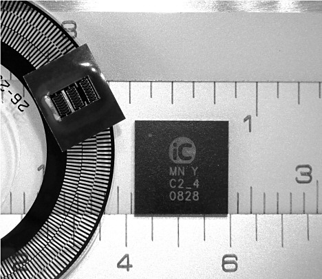 Figure 1. The optical nonius system with interpolation on three signal tracks |
In the case of the iC-MN, the interpolation circuit defines the absolute angle position using the phase shift of three sine signals. This approach requires lower accuracy than would be the case if there were just two scales.
Master track α1 is responsible for both the fine resolution and absolute system precision, whereas nonius track α3 and segment track α2 generate the information needed to determine the interval (Figures 2 and 3). Step-by-step computation increases the permissible tolerance for signal errors, which means little demand is made of the measurement scale and the encoder mechanics—and the leeway can be exploited for smaller sensors. The signal frequencies that occur are about the same size, so differing phase delays through analog circuit components with low-pass characteristics can be ignored.
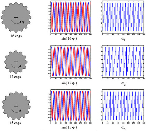 Figure 2. Three sine/cosine input signals digitized separately (phase angles α1, α2, and α3) (Click image for larger version) Figure 2. Three sine/cosine input signals digitized separately (phase angles α1, α2, and α3) (Click image for larger version) |
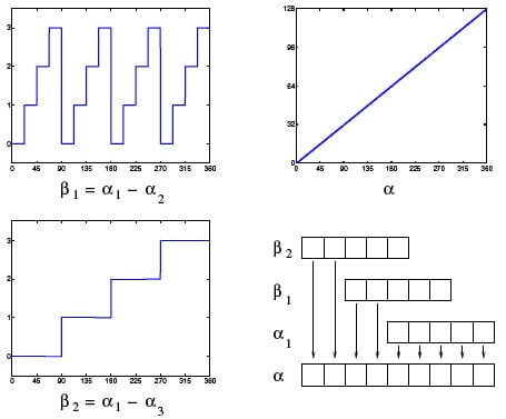 Figure 3. Angle α calculated from the phase shift β1 and β2, with α1 providing the fine resolution |
Chip Functions
Each of the iC-MN channels has an adjustable signal conditioning unit, with a sample-and-hold stage that halts the conditioned analog signal for sequential digitization. To this end, the unit includes a high-precision SAR ADC, with adjustable interpolation resolution of 8–13 bits.
In the analog path, the signal offset voltages provide a reference for calibration. The unit also evaluates signal amplitudes and, if required, tracks the energy supply of the sensor. This means the conditioning parameters set at room temperature remain valid across the entire operating temperature range.
The nonlinear ADC uses the tangent function to analyze the sine and cosine simultaneously. This prevents the ADC from interpreting frequency-dependent angle errors as velocity errors.
To compute high-resolution angle positions, you can configure two- and three-track nonius calculations, which enable resolutions as high as 25 bits (0.04 arc-seconds from 360°).
The converter measures 7 by 7 mm in QFN48, is protected at the cable end against reverse polarity and false connections, and contains an RS-422 transceiver serial data interface. Data is output in an SSI or BiSS protocol at clock rates of up to 10 Mbps.
With this device, you can monitor all the main functions on the chip and configure alarms for specific conditions. The system recognizes typical sensor errors—such as loss of signal due to broken wires, short-circuiting, dirt, or aging—and notifies the controller.
Optical Encoders
Absolute optical encoders use precise scales, with microstructures applied to a glass substrate. The devices profit from system-on-chip integration in terms of resolution and component size. In addition to performing multitrack scanning of digital codes, the encoders interpolate analog signals to generate interim values.
Optical encoders in throughbeam mode use LEDs as sources of illumination, a code disc with several tracks, and a light-sensitive sensor IC. The sensor combines a photodetector, signal conditioning unit, and interpolation circuitry in a single system-on-chip.
Standard technology achieves very fine resolution by using a high number of periodic divisions, which are distributed around the circumference of the code disc. The iC-LG system-on-chip position sensor, for example, initially divides each revolution into 2048 equal intervals. A code disc with a diameter of 42 mm has structural widths of ~27 µm on the code disc.
To maintain the absolute position across a single revolution, the sensor must differentiate between each periodic division. For this purpose, the code disc has up to 13 additional tracks, which provide clear information on the interval in the form of a digital absolute code.
The sensing device further refines the position value through the interpolation of the periodic divisions. Here, each division provides a sine and a cosine signal. By calculating the tangent function, the sensor can determine the actual phase angle within an interval. This can then be offset against the digital absolute code to obtain much finer absolute information on the position, with a resolution as high as 21 bits.
The Nonius Trick
To achieve fine basic resolution, nonius-based evaluation also distinguishes between periodic divisions. For this purpose, the approach uses additional sine signals instead of digital absolute codes. For the measurement scale, three tracks are sufficient instead of 12. Sensor, LED, and lens now fit into much smaller device designs, opening up new applications.
At the same time, active photosensor arrays, such as the iC-LSH, provide hysteresis-free and low-distortion sine signals in hi-fi quality. This enables finer interpolation so that nonius evaluation can be based on fewer periodic divisions (Figure 4).
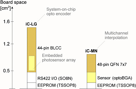 Figure 4. The waiving of digital absolute codes halves the space required and enables smaller encoders to be assembled |
Angle Errors
To achieve better interpolation, it's important to recognize relevant signal errors and compensate for them. Typical sources of error include a sensor encumbered by its offset (OS and OC); varying sensitivity between the sine and cosine sensors (amplitudes AS and AC); a phase shift between the sine and cosine signals that deviates from 90° (φSERR and/or φCERR), and nonlinearity in the characteristic curve of the sensor (deviation of the sine shape FSIN and/or FCOS). You'll also find errors in the measurement scale or grating, such as fluctuation in the width of the periodic divisions, with which the length of the sine and/or cosine periods would vary. In general, the angle can be calculated within a periodic division from the arctangent of the quotient of sine and cosine signal according to Equation 1:
 | (1) |
The interpolation circuitry quantizes the angle. It is this fine division of the periodic divisions that makes position encoders with resolutions of over 20 bits per revolution feasible.
A short-wave angle error is an error within a periodic division. Depending on the number of periodic divisions, the error has a varying degree of influence on the absolute accuracy of the angle measurement.
A long-wave angle error repeats itself once per revolution of the axis. The adjustment of the code disc usually causes this type of error. The precision of the measurement scale is also a decisive contributing factor. The placement of the position encoder on the axis (e.g., off-center mounting and force action on the axis and bearings) can also cause angle errors across the entire system.
For an optical encoder, an absolute error across a full revolution of <0.014° (50 arc-seconds), with 2048 periodic divisions, would correspond to an error of ~28°, with reference to the 360° of an electric signal period. Interpolation circuitry can improve accuracy by a factor of ten, so that the number of periodic divisions can be accordingly reduced.
You must, however, compensate for the lower resolution of the measurement scale with signals that have greater interpolation ability. Signal conditioning is also an important factor. It must permit very fine corrections to keep the absolute error to the figures mentioned earlier.
The sensor signal's harmonic content also has an effect on the interpolation result because it reduces the angle accuracy. The total harmonic distortion obtainable with modern photosensor arrays of well under 0.4% (with 256 periodic divisions) does not, however, constitute a dominant error source.
Summary
Thanks to nonius interpolation, measurement systems with scalable performance can achieve greater integral accuracy for angle encoders and higher resolution with good differential precision for digital motor feedback systems.
A relatively small optical sensor is sufficient to scan position information represented by the phase relationship of just a few signals. This simplifies illumination, uses less energy, and saves space. This in turn reduces system costs and opens up new applications.