
Introduction
Most of today's electronic applications are designed to be "aware." Cars are aware when it is night time or when it is raining, so they can automatically turn on the lights or the windshield wipers. Some watches are aware of rapidly changing weather so hikers can take shelter rapidly. Even homes can be aware when we have returned, so they can adjust many comfort and security systems accordingly.
However, most of the applications, in order to be "aware," still rely on humans to tip them off on certain events or conditions before they can carry on accomplishing their tasks. They usually achieve this "awareness" by using dedicated sensors or a human-interface input system, all initially relying on analog information that needs to be digitally processed by a microcontroller (MCU). This makes analog-to-digital conversion (ADC) and data acquisition a highly strategic part of global application processing.
The main challenges pertaining to data acquisition will relate to code space, which is required to remain as small as possible. Therefore, code size requirements come with simplicity and flexibility. Another challenge to such applications is the processing speed, which is usually expected to be high and which goes along with a last important challenge to be considered, the lowest power consumption.
As an example of one solution, Microchip's eight-bit PIC MCUs now include the PIC12/PIC16LF155X family offering an integrated hardware capacitive voltage divider (CVD). The CVD is a capacitive-touch acquisition method for human-interface input systems. All of these MCUs feature at least one 10-bit ADC module, capable of delivering 250 ksamples/s. Some family members integrate two ADC modules, which, when combined with the Hardware CVD feature, takes a lot of acquisition-related complexity off the CPU.
Example Of An 'Aware' Application
A coffee maker provides a good example of how the previous challenges of minimizing code space, maximizing processing speed and minimizing power consumption can be overcome. Even though this type of application can embed many more sensors for its "awareness," we will be focusing on a few for the sake of simplicity.
This application needs to know when its water tank gets too low, so it can stop brewing coffee. It also needs pot-presence, or absence, information, so it can allow the brewing to continue only in the presence of this element. Another type of useful information is the level of coffee in the pot, which instructs the coffee-pot heating system to shut down if the liquid gets too low. The coffee maker also needs to sense the coffee temperature to maintain the liquid at a constant, possibly user-specified value. Finally, because such an application usually needs some kind of programming, i.e., start time, date and time management, etc., it requires some interaction with the user. This is done using a touch keypad and a small LCD display, as shown in figure 1.
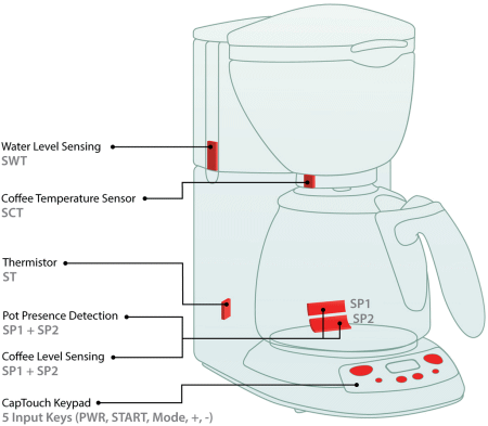
Fig. 1: Coffee Maker Application
In the example, capacitive sensing is used for all mentioned sensors except for the coffee temperature, which uses an infrared (IR) sensing method for its non-intrusive aspect (no direct contact with the coffee), and the brewing temperature control, which relies on a thermistor. Capacitive sensing is easy to implement, as it requires no specific material other than what is typically utilized in a standard board design. Sensors can be built as regular copper pads of any shape and size, and can be placed on a regular PCB. Other sensor implementations are also possible.
Another significant advantage of capacitive sensing is its high cost efficiency. If we consider the different sensing implementations only a brief description of their principles is provided below:
- Water Tank Level Sensor: Because the water tank is unmoveable, this sensor can be designed as a single copper pad located outside the tank, and can use the water's dielectric constant to measure its coupling to the liquid in the tank. An MCU is easily capable of tracking and differentiating the amount of coupling in the presence of water from the amount when there is none left. If more accuracy in the water-level detection is required, then several sensors can be used in a slider-like configuration, which enables the definition of multiple levels with just a few sensor pads. For example, a three-sensor system can detect tens of positions or water levels. This system can be further improved to compensate for temperature changes by using an additional sensor as a reference input for the CPU to compare against, which also eliminates the need for recalibration. This sensor can be placed on the same PCB, facing the opposite direction as the main sensor.
- In-Pot Coffee Level Sensor: Here, the liquid level in the pot can be monitored using the same method as the water tank. The system could use a single sensor pad on a regular PCB. A challenge would come from the fact that the coffee pot is a moveable part. This creates an air gap between the sensor pad and the liquid, including the pot glass, which will substantially affect the sensor's sensitivity. The selection of the material and an acceptable thickness for the product's casing will help ensure good sensitivity. The air gap between the pot and the casing will also significantly impact the sensitivity. A typical set of materials including plastic casing of about 2 mm with an air gap of about 1 mm followed by a 2-mm thick pot, should provide good readings and the detection of the presence of coffee in the pot at a given level. This detection can be further enhanced by adding one or more sensors to measure multiple levels for the liquid in the pot. This makes it possible to keep the quantity of coffee at a given value (see figure 2).
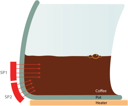
Fig. 2: Pot Presence and Coffee Level Sensor Layout
- Coffee-Pot Presence Sensors: This can use either SP1 alone, in the case of a single-sensor layout in self-capacitance sensing, or SP1 and SP2, in a dual-sensor layout as described above to be driven in mutual sensing for increased sensitivity. In this case, we are interested in the presence of glass alone or glass and liquid, which can be factory-modelized very easily. Knowing that the air's permittivity significantly degrades the sensitivity of the system when the pot is absent, an MCU will easily be able to detect when the pot,or some other object, is present as the readings acquired in this case will show relatively low values. By adequately setting a threshold value, a CPU will be able to distinguish when the pot is present from when it is absent.
- In-Pot Coffee Temperature Sensor: The choice of IR to read the liquid's temperature is driven by the non-intrusive aspect of this method. Another reason is its contactless aspect, because of the mobility of the coffee pot and the liquid to be sensed. Taking into consideration that the application is "aware" of whether the coffee pot is present or absent, and also whether there is enough liquid in it, it is completely capable of basing its acquisitions off the combination of these two events. The acquisitions do not use the main CPU's ADC as we selected a standalone IR sensor that delivers the expected data over SMBus/I²C communications, already in digital and ready to be processed.
- In-Brewer Coffee Temperature: This task is part of the brewing process and can be handled by the main CPU. The temperature data acquisition for this sensor is straightforward. The principle relies on the variation in the voltage of the thermistor as the temperature being sensed changes.
- Capacitive-Touch Keypad: This is a way to interact with the user. This keypad has five keys, also called touch sensors. The data acquisition part of it is based on Microchip's CVD method, which features noise robustness and increased sensitivity. The recommended keypad overlay for this type of application is metal-over-capacitive (MoC), to achieve water immunity when being cleaned. If a metal overlay is not feasible for the design, Microchip's mTouch solutions offer water resistance in a standard capacitive-touch approach that eliminates the effect of water at the signal level, rather than relying on firmware techniques to try to eliminate the effect of water with pattern matching. Another advantage to selecting MoC is the fact that it still detects button presses with gloved fingers.
This application requires the five sensors listed below, but could use more or less, depending on the specified functionalities.
- [PWR] Power button allowing it to turn the coffee maker ON and OFF
- [Mode] Allows navigation of the current time display and setup modes, as well as brewing time display and setup modes.
- [+] [-] To increment or decrement values in setup modes
- [START/STOP] To immediately start or stop the brewing process.
Here the sensors are regular PCB pads, using a spacer layer and a metallic front panel. The system senses the value of the capacitor created by the copper pad and the front panel. A finger press on the panel causes a small deflection that decreases the distance between the previously described plates, which increases the capacitance value. The system scans all the sensors in sequence, looking for a shift in each capacitance value. The scan sequence starts over at a specified period of time.
Hardware Considerations
Figure 3 shows that such a design only requires few electronic components, which will keep the cost of the hardware at a minimum level.
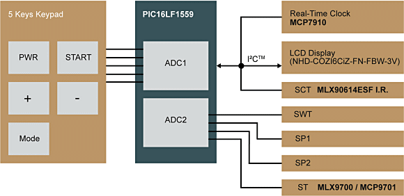
Fig. 3: Coffee-Maker Hardware Diagram
The coffee maker uses 10 sensors, overall. Nine of them deliver analog information, which requires nine ADC channels. The PIC16LF1559 is a good candidate to accomplish the task, as it features a maximum of 17 input channels in a 20-pin package. It also features I²C/SMBus communications. More importantly, it offers two high-speed ADC modules, each with hardware CVD, which frees the CPU from a significant amount of processing pertaining to capacitive-touch input sensing for the keypad.
The hardware CVD acquisition allows better control of the acquisition timing, which in turn will have significant impact on the keypad's noise response and sensitivity. Also, the unique dual-ADC configuration of this MCU family of devices allows, in this case, dedicating one ADC to continuously operate in hardware CVD acquisition mode, while the second can be dedicated to handling the other sensing methods.
The LCD display needs to be accessed over I²C with this MCU configuration to keep the number of required pins to a minimum of two. Moreover, the utilization of this bus opens up new possibilities to add more I²C devices, such as the real-time clock management device or the IR temperature sensor SCT used to sense the in-pot coffee temperature without having to use additional pins on the MCU.
Software Considerations
In traditional sensing systems with just one standard ADC peripheral, the hardware configuration described above would require the application to switch to and from different modes. In our case, the switching mainly happens from mTouch (keypad scan) to other sensing methods. The dual-ADC configuration takes a significant amount of the ADC configuration code (the switching code) away as we dedicate one ADC to the CVD acquisition and the second ADC module to all the other sensing methods. This also optimizes processing time in time-critical data acquisition.
If we consider the CVD acquisition only, when it is done in software it requires that acquisition code snippets get copied over for each sensor; for finer control of the acquisition timing and a better noise response. The introduction of hardware CVD removes significant code overhead, freeing the CPU from all the related processing and allowing it to focus on some other tasks if needed. Table 1 shows the benefits of using Hardware CVD in capacitive touch inputs by comparing the acquisition code size generated with this peripheral, for several sensor configurations, to the code required for a pure software implementation. We can see that, for our particular touch-sensor configuration, the related acquisition code shrinks close to half the size of the fully software approach (56.7%).
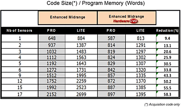
Table 1: Code Size/Program Memory
This feature also leads to much simpler code, as the CPU actions become just a matter of accessing registers to initiate the acquisition, and ultimately to read the expected data. The application and the CPU still need to manage some more filtering and event decoding, after the raw readings become available.
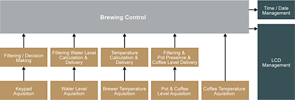
Fig. 4: Coffee-Maker Software Diagram
All sensing methods benefit from the 250 ksamples/s capability of each ADC module, which doubles the overall throughput to 500 ksps because they are independent and can perform true simultaneous conversions.
The coffee-maker keypad, which could also apply to other sensing methods, benefits from another nice feature of this MCU, where the peripheral can scan its sensors all at once in a single reading and provide a single value, combining the states of each sensor as if they were seen as a single virtual sensor. This single reading is then delivered to the CPU, which uses it to determine whether any of those combined sensors has generated a button-press event. Once an event has been confirmed, the CPU can request individual sensor scans to identify which key has been pressed. This mechanism can be used when the system is in low-power scanning mode, as the system scans the keypad much faster (in a single-scan operation) and can therefore return to sleep faster and thereby saving extra power consumption.
The coffee-maker software takes advantage of another nice feature offered by the PIC16LF1559 MCU: the periodic conversion. The ADC modules do not require the CPU to initiate the conversions, as they are fully capable of handling such an action based on hardware-timer overflows and in complete autonomy. The CPU is notified only when a reading is available, allowing it to remain in a low-power mode when needed, and keeping the power consumption of the system to a minimum level.
Summary
So, looking back into the example coffee maker's sensor acquisition process, the choice of the PIC16LF1559 as the main MCU turns out to be strategic because the application takes full advantage of the MCU for three unique design parameters:
- Code size: The MCU offers many ADC features including hardware CVD that reduce overall code size because they provide many automated processes that free the CPU from the acquisition workload. Also, the unique dual-ADC configuration enables dedicating each module to a different type of sensing method, further reducing extra code overhead.
- Flexibility: The ADC modules can operate either in collaboration or in complete independence. In the example application, independence is an important factor. They also offer multiple features designed to only provide information to the CPU as it becomes available, i.e., raw readings, etc.
- Low-Power: In addition to the fact that the MCU uses Microchip's eXtreme Low Power (XLP) technology, the ADC modules have been designed with the objective of taking load off the CPU. This enables it to operate in low power mode for a long period of time whenever necessary.
About the Author
Lyes Garidi is a Principal Applications Engineer for Microchip Technology Inc. He currently works in the Human-Machine Interface Division (HMID).
Related Stories
Touchless Sensing Technology Represents the Next Paradigm in Human-Machine Interface
Making the "Connected Factory" a Reality