
Traditional linear position technologies such as linear contacting potentiometers, linear variable differential transformers (LVDTs), magnetostrictive sensors, and linear encoders vary by stroke, resolution, cost, environmental resistance, as well as reliability, as depicted in the comparison chart in Figure 1. Understanding the differences between the sensing technologies can help you decide on the best one based on performance, price, and cost of ownership. Let's consider the four main technologies: potentiometers, LVDTs, encoders, and magnetostrictive sensors.
 Figure 1. Attribute comparison chart of the main linear position technologies |
 Figure 2. Circuit diagram for a basic potentiometer where Ei is the input voltage and Eo is the output voltage |
Potentiometers
A potentiometer is basically a three-terminal voltage divider powered from an AC or DC source. Two terminals are fixed, while an output terminal (slider), connected mechanically to a moving member, moves up or down to represent displacement. The supply voltage is applied to the fixed terminals and the output signal is ratiometric with respect to the applied voltage (Figure 2). While low-cost potentiometers are constructed from deposited thick-film resistive material, more expensive versions are made from wirewound resistance material and are capable of dissipating more power than thick-film potentiometers.
Although linear potentiometers are economically priced, easy to implement, and have a short body length, these devices rely on mechanical contact to provide position feedback and thus exhibit poor repeatability and larger hysteresis. Outputs tend to deteriorate over time due to contact wear, particularly under high vibration conditions. In operating conditions such as high shock, vibration, immersion in liquids, and high temperature, the mechanical contact (or slider) can experience an open circuit, limiting the sensor's performance and reliability. The mean time between failures (MTBF), a key parameter for longevity, is fewer than 1000 hr., as long as the environment is moisture-free and with little or no vibration. Potentiometers, used as controls in consumer electronics in the 1990s, are more widely used today in volume controls and as position sensors.
LVDTs
LVDTs, sometimes referred to as linear position sensors, consist of three windings, a ferromagnetic core, and a housing, as shown in Figure 3. Voltage is applied to the primary winding from an AC source with temperature-stable frequency and amplitude. Typical frequency and amplitude values are 5 kHz and 3 Vrms, respectively. Two secondary windings pick up the signal that is induced from the primary core by the core's position.
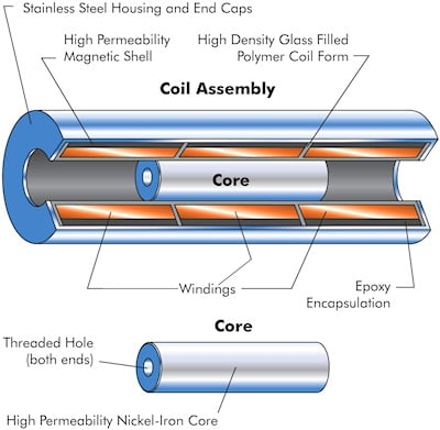 Figure 3. A cutaway photo of an LVDT showing the windings and core |
 Figure 4. The electrical schematic for an LVDT |
The core, made from 52 iron-nickel alloy, is usually attached to a moving member whose displacement is being measured, as shown in the schematic in Figure 4. If the core is in the middle of the LVDT, both secondary coils produce equal and opposite signals that together produce a null voltage. At this point, the phase angle will also change by 180° as the core moves from one coil to the other; this phase angle determines the polarity of the signal and gives the direction of the displacement. If the core is moved off-center, the mutual inductance of the primary with one secondary will be greater than that with the other, and a differential voltage will appear across the secondaries in series; for off-center displacement within the range of operation of the LVDT, this voltage is essentially a linear function of displacement. Usually the AC output voltage is converted to a high-level DC voltage or current that is more convenient to use.
Because LVDTs are very versatile, noncontacting, and robust, they offer long-term reliability in harsh or hostile environments and their frictionless operation translates into higher repeatability and resolution.
The sensors require AC signal conditioning or support electronics that may either be contained within the sensor, such as a DC-operated LVDT, or located remotely, while the sensor itself remains in a harsher environment. By using a low operating frequency range between 2–4 kHz, the LVDT and signal conditioning can be separated by distances up to 40 ft. LVDTs are available in full-scale ranges of ±0.01 in. to ±10 in. (±0.25 mm to ±250 mm).
LVDTs are typically used in systems where high reliability is desired, such as aircraft wing-flap indication, subsea applications, high-temperature steam valves, and power plant installations (Figure 5). For the AC-operated LVDT, the MTBF can be up to 5,000,000 hr. With special packaging and high-temperature materials, working temperatures can range from –200°C to 500°C.
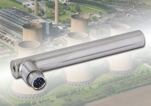 Figure 5. An LVDT used for steam turbine valve control in a power plant where reliability and longevity are key parameters. The LVDT used in this application is constructed of stainless steel and can withstand temperature spikes to 400°C and exposure to radiation at 3 × 10⁷ Rads for 40 yr. |
In the past, LVDTs suffered from two problems: cost and space requirements. For example, to measure a stroke length between 0–10 in., the length of the LVDT could be as long as 23 in. Modern layer-winding techniques and low-cost ASIC/microcontroller-based electronics compensation techniques are addressing these issues, making the LVDT more attractive in many applications traditionally served by potentiometers and magnetostrictive sensors.
Encoders
Linear encoders employ optical or magnetic gratings that supply a stream of digital signals that are decoded by the read head to provide absolute or relative position measurements. Low-cost encoders provide resolutions from 10–12 bits while high-end units provide 18-bit resolution. There are two types of encoders: absolute and incremental. Although absolute encoders do not lose position when switched off, incremental encoders do, requiring the use of a home position sensor. Incremental encoders give a pulse train output that indicates units of movement while absolute encoders provide a binary signal scaled in bits of resolution.
Incremental encoders read linear graduations etched on a glass scale or sense magnetic poles deposited with uniform spacing on a ferromagnetic material. While known for high precision, their limited frequency response often makes linear encoders better suited for slower dynamic applications. The devices also require complex electronics to generate absolute position measurements and tend to be expensive. Linear encoders are used in applications such as positioning tables and labs and are also popular in motion control systems, robots, and machine tools, where their relative fragility and high cost can be accommodated. The MTBF value ranges from 100,000 hr. to 1,000,000 hr., subject to the operating environment.
Magnetostrictive Sensors
Magentostrictive sensors employ a position sensing magnet, a wave-guide, a pick-up coil, and electronics to precisely measure the position of a moving part. The magnet is attached to the machine tool, hydraulic cylinder, or whatever is being measured. The waveguide wire is enclosed within a protective cover and attached to the stationary part of the machine or hydraulic cylinder.
The location of the position magnet is determined by simultaneously starting a timer and applying a current pulse to the waveguide. The current pulse generates a sonic wave at the location of the position magnet via the Wiedemann effect—a twisting of a ferromagnetic waveguide caused by the combination of a longitudinal magnetic field and a circular magnetic field. The sonic wave travels along the waveguide until it is detected by the pickup, which stops the timer. The elapsed time indicated by the timer represents the distance between the position magnet and the pickup. The sonic wave also travels away from the pickup; to avoid an interfering signal from waves traveling in this direction, energy is absorbed by a damping device (called the damp). The pickup makes use of the Villari effect, the change of a material's magnetic properties when it is subjected to a mechanical stress.
A small piece of magnetostrictive material, called the tape, is welded to the waveguide near one end. This tape passes through a coil and is magnetized by a small permanent magnet called the bias magnet. When a sonic wave propagates down the waveguide and the tape, stress induced by the wave causes a wave of changed permeability in the tape. This, in turn, causes a change in the tape's magnetic flux density resulting in a voltage output pulse from the coil (an example of the Faraday effect). This voltage pulse is detected by the electronics and conditioned into the desired output.
Widely used for long stroke measurements in cylinders, actuators, and simulators, magnetostrictive technology is very accurate but typically expensive and limited to benign applications, where severe shock, vibration, and temperature extremes are not present. The MTBF for these types of linear sensors can range from 100,000 hr. at 85°C to 250,000 hr. at 25°C as long as vibration is minimal. Units are particularly useful for relatively long measurement ranges, typically from 6–120 in. (150 mm to 3 m) or more. Figure 6 shows the operational function and key components of a typical magnetostrictive sensor.
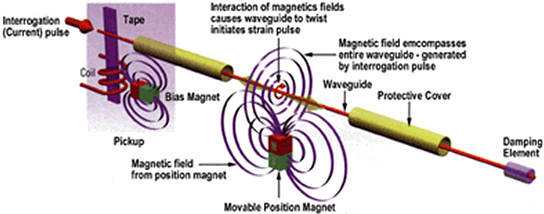 Figure 6. A diagram of a typical magnetostrictive sensor |
Summary
In critical applications where the cost of ownership, safety, and reliability are major concerns, LVDTs are the appropriate choice, subject to measuring range and package envelope criteria. With its MTBF advantage over other position technologies, the LVDT remains the main choice for nuclear, high-temperature, high-vibration and shock, subsea, power generation, and other critical applications.
ABOUT THE AUTHOR
Karmjit Sidhu is VP of Business Development for Macro Sensors, Pennsauken, NJ. He can be reached at 973-448-1901 or [email protected].