
Ultrasonic level sensors have been on the market for years and are still considered a trusted technology throughout the process measurement industry. Ultrasonic transmitters are noncontacting and offer a cost-effective choice for most straight-walled tank-level applications. Over the years, however, newer level measurement devices have emerged that are capturing market share from older technologies that use sound or echo-based measurement. Technologies such as guided-wave radar (GWR) are comparably priced and have proven to be a more reliable choice in difficult sensing conditions. Guided-wave radar is suitable for both liquid and solid applications and operates independent of process conditions.
Ultrasonic Technology
Ultrasonic transmitters operate by sending a sound wave generated from a piezoelectric transducer to the surface of the process material being measured. The transmitter measures the length of time it takes for the reflected sound wave to return to the transducer. A successful measurement depends on the wave, reflected from the process material and moving in a straight line back to the transducer. Because factors such as dust, heavy vapors, tank obstructions, surface turbulence, foam, and even surface angles can affect the returning signal when using an ultrasonic level sensor, you must consider how your operating conditions can affect the sound waves.
Other important aspects of ultrasonic transmitters include:
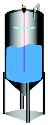 Figure 1. Ultrasonic transmitter mounted on top of tank |
- Sound waves—Sound must travel through a medium, usually air, making the transmitters unsuitable for use with vacuum applications where the absence of air molecules prevents the propagation of sound waves.
- Surface condition—Foam and other debris collected on the surface of the liquid can absorb the sound waves and impede their return to the sensor.
- Angles of incidence and reflection—Sound waves must be sent and received in a straight line and reflective surfaces must be flat (i.e., nonagitated/nonturbulent condition).
- Operating temperature—Ultrasonic units are typically plastic with a maximum operating temperature of 60°C. Also, varying process temperatures may generate inaccurate level readings.
- Operating pressures—Ultrasonic devices are not intended for extreme pressure limits; maximum working pressures should not exceed 30 psig.
- Environmental conditions—Vapor, condensing humidity, and other contaminants can change the speed of sound through air and greatly affect the accuracy of the return signal. As a result, ultrasonic devices should be mounted in a predictable environment.
The most popular benefit of through-air measurement technologies such as ultrasound, radar, and laser measurement is that the measuring device never comes in contact with the product being measured (Figure 1), although at some point the measuring signal must come in contact with the liquid surface before it begins its return trip back to the sensor. This explains why the air quality between the sensor and liquid surface can be problematic and why the quality of the liquid surface needs to be accounted for. Every disturbance the signal picks up on its way to the liquid surface and back will affect the level measurement information in the signal.
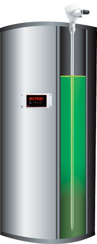 Figure 2. GWR technology measuring liquid level in process vessel |
Guided-Wave Radar (GWR)
Guided-wave radar (GWR) is a contacting level measurement method that uses a probe to guide high-frequency electromagnetic waves from a transmitter to the media being measured (Figure 2).
GWR is based on the principle of time domain reflectometry (TDR). With TDR, a low-energy electromagnetic pulse is guided along a probe. When the pulse reaches the surface of the medium being measured, the pulse energy is reflected up the probe to circuitry that then calculates the fluid level based on the time difference between the pulse being sent and the reflected pulse received. The sensor can output the analyzed level as a continuous measurement reading via an analog output, or it can convert the values into freely positionable switching output signals.
Unlike older technologies, GWR offers measurement readings that are independent of the chemical or physical properties of the process media with which it is in contact. Additionally, GWR performs equally well in liquids and solids.
GWR is suitable for a variety of level measurement applications including those that involve:
- Unstable process conditions—Changes in viscosity, density, or acidity do not affect accuracy.
- Agitated surfaces—Boiling surfaces, dust, foam, and vapor do not affect device performance. GWR also works with recirculating fluids, propeller mixers, and aeration tanks.
- High temperatures and pressures—GWR performs well in temperatures up to 315°C and can withstand pressures up to 580 psig.
- Fine powders and sticky fluids—GWR works with vacuum tanks filled with used cooking oil as well as tanks holding paint, latex, animal fat, soybean oil, sawdust, carbon black, titanium tetrachloride, salt, and grain.
One of the most common misconceptions about GWR is how product build-up on the probe affects the level measurements. One would think that if you have a mass of product stuck to the probe, or a coating of product over the probe's entire length, that the signal would misidentify the true liquid surface (Figure 3). This is not the case. The GWR radar signal has a very large detection area—360° and extending out several feet—around the probe. When the electromagnetic pulse comes in to contact with a mass of product on the probe, the signal is returned and analyzed to see whether it reflects the true liquid level (Figure 4). Because the true liquid level always has a larger return signal than the return signal generated from the smaller mass sticking to the probe, the sensor can easily identify the liquid surface. Algorithms developed over the last decade have made this contacting form of level measurement an excellent choice for even the stickiest of fluid-level applications.
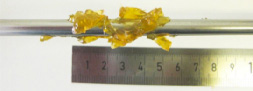 Figure 3. Sticky product covered over a 2 in. length of 1/4 in. o.d. rod probe | 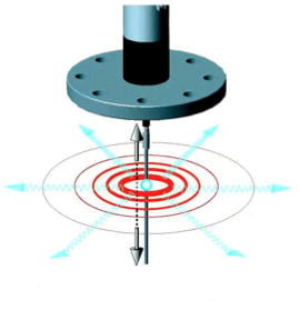 Figure 4. Sound energy pulse advances outward from the probe surface |
Comparison Points
The chart in Figure 5 compares some important comparison points between ultrasonic and GWR transmitters:
Figure 5. A comparison between ultrasonic and GWR transmitters
| Ultrasonic transmitters | Guided-wave radar transmitters |
| Measurement Principle | |
| Sound waves | High-frequency radar impulses |
| Contact Type | |
| Noncontact measurement | Contact measurement |
| Operating Limits | |
| Limited operating pressures and temperatures | High temperatures and pressures do not affect device performance |
| Mounting | |
| Top-mounted | Top-mounted |
| Environmental and Application Conditions | |
| Conditions affect measurement performance | Not affected by environmental and application conditions |
| Overall Performance | |
| Acceptable Performance is based on strength of the reflected sound wave or echo | Exceptional Performs well independent of process conditions |
ABOUT THE AUTHOR
Dave Grumney is President of Flow Line Options Corp., Macedonia, OH. He can be reached at 877-356-5463, [email protected].