

Advanced technology industries such as defense, satellite communications, telecom, medical spectrometry, avionics, and industrial test equipment develop electronic systems that have taken a giant step forward over the past few years as design engineers strive to keep pace with the increasing capacities—faster processors and greater bandwidth—of digital electronics. Although processors and interfaces with gigahertz performance have been available for some time, it is only recently that ADCs with adequate resolution and data rates have become available. As electronic digital systems have become faster, the limiting factor for fully digital implementations has become the speed and resolution of the ADC, requiring the ADC designers to find effective component solutions.
Ultra-high-speed Converters
High-grade, ultra-fast ADCs are tailored for high-performance markets such as those requiring sampling speeds >1 Gsps and have the following characteristics:
- High sampling rate
- High bandwidth—the converter bandwidth can be >5 GHz
- Low latency—minimal pipelining is used, which means latencies as low as 2 clock cycles
- Minimum input voltage range
- Bipolar technology—this minimizes switching transients
The 8-bit EV8AQ160 and the 10-bit EV10AQ190 families of quad ADCs are part of e2v's product line. These components contain many advanced features to enable them to operate at high sample rates; these same features can also be used to improve the system's flexibility and ease of use.
As we see in the block diagram in Figure 1, a quad converter contains four ADC cores and a track-and-hold amplifier (T/H). Timing generators and logic circuits control the system and the cross-point switch is located at the front end. The cross-point switch allows any input to be switched to any of the cores; it also allows any single input to be switched to all of the cores at once. This is done with minimal crosstalk and without limiting the bandwidth of the ADC. With the cross-point switch, the cores can also be used in interleaving mode where the sample point of each core is phased, increasing the overall sample rate by a factor of two or four times the rate of the individual cores, depending on the interleaving scheme. The quad ADCs can have four channels operating at 1.25 Gsps , two channels operating at 2.5 Gsps, or one channel operating at 5 Gsps.
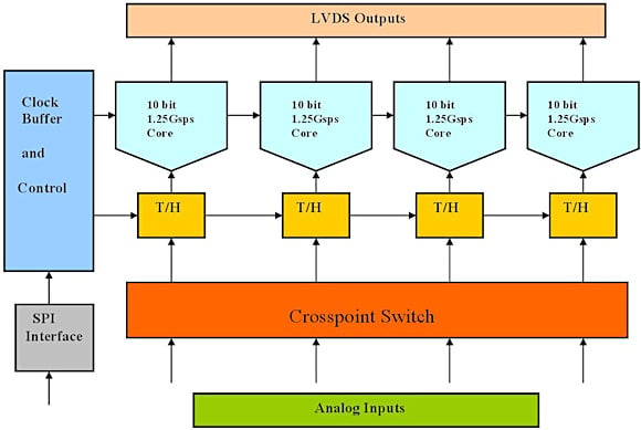 Figure 1. Internal system diagram of a quad 10-bit ADC |
Applications
Traditionally, these devices have been used in military applications such as radar and electronic countermeasures that require high sampling rates and large bandwidths. Scientific instrumentation for high-energy physics and radio astronomy has also always required the highest levels of performance. Today, however, several other markets require these performance levels and these include test instrumentation (e.g., oscilloscopes and spectrum analyzers); COTS board manufacturers of PCI, military software-defined radio, radar, and electronic counter-warfare (ECW); semiconductor automatic test equipment (ATE); high-speed hard disk test equipment; and laser distance measurement systems.
Several other, higher-volume markets are poised to need very high-speed A/D conversion as the bottleneck at the ADC becomes more of an issue for new broadband services such as telecom test equipment, telecom infrastructure (e.g., base-stations and fiber-optic communications), and medical imaging such as nuclear magnetic resonance (NMR), ultrasound, and positron emission tomography (PET).
Frequency domain applications. Software-defined radio (SDR) is the holy grail of radio development. The SDR Forum defines an SDR device as one that functions independently of carrier frequencies and can operate within a range of transmission protocol environments. As such, the ideal SDR would have the RF interface to a power amplifier in the transmit path, a low-noise amplifier in the receive path, and little or no analog filtering. Upgrading or changing the features of this ideal radio would be accomplished by uploading new software, a valuable feature in systems that need to achieve interoperability. The SDR can also simultaneously monitor many frequencies, which is invaluable for radar systems or electronic warfare where it enables the detection of echoes or jamming threats.
Because quad ADCs have the ability to change sample rate (at the expense of input channel number) they are useful in multiple-array applications—such as radar and ultrasound—that need to scan as large a bandwidth as possible while maintaining the flexibility to increase the number of channels if required.
Time domain applications. In scientific instrumentation, quad ADCs are typically used in the capture of high-speed signals that result from particle collisions, mass spectroscopy, or from X-ray diffraction.
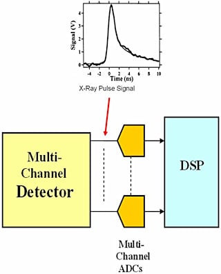 Figure 2. Typical multichannel experiment |
The example in Figure 2 shows the signal emitted from a typical X-ray experiment. In this type of experiment, multiple detectors are required to improve the signal to noise ratio and therefore increase the chance of detecting rare events. The detectors used are often multiwire proportional counters (MWPCs), microchannel plates, or silicon strip detectors, all of which convert the incoming particle or photon into an electrical charge and localize its position. For these experiments, the important characteristics for the ADC are the gain stability and the ability to adjust gain for calibration reasons.
Oscilloscopes are another important time-domain application. With oscilloscopes, the sample rate is of great importance and it is common to interleave multiple ADCs. When using interleaving, it is important to ensure that each ADC is accurately matched in terms of gain, offset, and phase of the clock signal. Any mismatch will result in discontinuities in the digital output that will affect the quality of the result. The internal structure of the e2v quad ADCs has gain, offset, and phase adjustment features for each input, ensuring full performance when all four cores are interleaved. These calibration features are stable over wide temperature ranges, typically ±30°C.
Using Quad ADC Features to Improve Performance
The ADC's calibration functions can also be used when the device is operating in standard four-channel mode, allowing the offset, gain, and phase adjustments to be used for system adjustments such as channel matching in terms of offset and gain and for the phase delay of each input.
In multiple-array systems—found in radar systems, ultrasound detection, and target guiding systems—each element of the array frequently must be phase-adjusted with relation to the other elements, as is the case with directional antennas. The diagram in Figure 3 shows the use of a multi-element array with the fine phase timing provided by the ADC's internal adjustment feature. In such an array, all the ADCs must be properly synchronized, which eases the postprocessing requirements in systems that contain multiple ADCs. A consistent synchronization procedure as part of the ADC's timing is essential for this type of system.
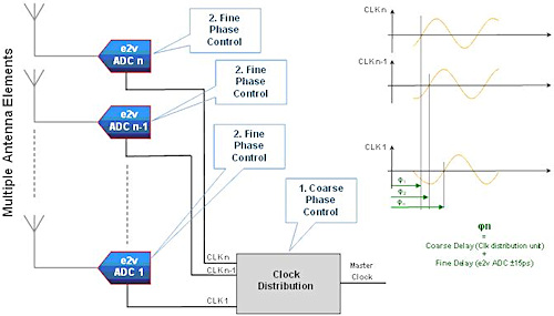 Figure 3. Phased-array antenna (Click image for larger version) |
In some scientific measurements, e.g., pulse-height spectroscopy, it is useful to have increased resolution for smaller signals. Using the quad ADC with a range of input gain amplifiers as shown in Figure 4 enables smaller pulses to be converted with higher resolution and higher dynamic range. Larger pulses would saturate the high-gain channels, but this condition can be detected by using the out-of-range bit output from the ADC or by postprocessing of the data.
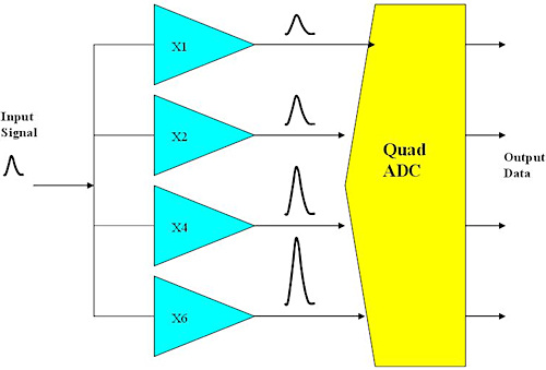 Figure 4. Stepped-gain ADC system |
Dither, which adds a noise-like, out-of-band signal to the input, could also be considered for pulse recording systems in order to reduce INL/DNL effects. The addition of noise has the effect of smoothing any INL/DNL shape in the ADCs response.
Quad ADCs' reprogrammability is especially useful in repetitive triggered or pulsed experiments. A zoom in the time domain can be achieved by reprogramming the ADC to operate at a higher sample rate thereby providing greater temporal precision.
Conclusion
Due to the internal matching of the devices, the use of quad, ultra-high-speed ADCs enables a reduction in component count as well as an increase in performance when compared to the use of discrete ADCs. In addition, the features that enable them to operate at high sample rates can also be employed in other ways to improve the overall system performance. The family of 8- and 10-bit quad ADCs from e2v offers flexibility and high performance, making them an ideal choice for many instrumentation and communication systems.
ABOUT THE AUTHORS
Andrew Glascott-Jones is an Application Engineer for e2v in Grenoble, France. He can be reached at [email protected].
Francois Bore is the Chief ADC Designer for e2v, Grenoble, France. He can be reached at [email protected].
Nicolas Chantier is Marketing Manager for e2v, Grenoble, France. He can be reached at [email protected].
Jean-Philipe Amblard is Data Converter Product Manager for e2v, Grenoble, France. He can be reached at [email protected].
Eric Marcelot is Marketing Director for e2v, Grenoble, France. He can be reached at [email protected].