
 Part 1 of this article, appearing in the October 1999 issue of Sensors, described the general applications, performance characteristics, theory, calibration, and design considerations of single-rotor, full-bore, axial turbine flowmeters. This type of turbine flowmeter is well known for numerous important mainstream applications.
Part 2 focuses on some of the different designs and other types of turbine flowmeter, including dual-rotor axial turbines, insertion axial turbines, and multijet turbines. Also, certain applications have unique design requirements and solutions that differ from those described in Part 1. Two of these, namely propeller meters for measuring water flows and certain types of spirometers, which are used in the medical field, are the starting point for this discussion. In the area of advanced applications, some of the research into the use of axial turbine flowmeters for the measurement of two-phase (gas/liquid) flows, in which there is continuing interest, is also briefly reviewed. Tangential turbines, sometimes referred to as impeller meters, are not addressed.
 |
| Photo 1. The Model 305 mainline propeller meter from Sensus Technologies, used for accountability measurements in irrigation systems, is available in 4–24 in. sizes. It is installed through a hole that must be cut into the side of the existing pipeline (template supplied). The meter is then sealed with a saddle-clamped buna-N gasket. The design incorporates a three-bladed, polypropylene rotor mounted by means of a ceramic bearing onto a ceramic-coated stainless steel spindle. This rugged design allows the meter to tolerate suspended solids, such as sand, without experiencing undue wear. As is typical for these types of meter, the rotor assembly is cantilevered from the top gear housing and features a magnetically coupled mechanical drive. The standard mechanical register can be equipped with an electronic transmitter. Working pressure is up to 100 psi and the accuracy is ±2% of actual flow over a flow range of 4:1 for 4 in. to 10:1 for 12 in. and larger sizes. (Photo courtesy of Sensus Technologies, Inc.) |
The figures and references are numbered consecutively from those in Part 1.
Propeller Meters
Propeller meters are used in municipal, irrigation, and wastewater measurement. Although in some designs propeller and turbine meters look almost identical and operate on the same axial rotor principle, this type of flowmeter is currently distinguished, both commercially and officially [14,15], as a category distinct from the axial turbine. Diameters of up to 2440 mm (96 in.) are available. The flow rate capacity of an 1800 mm (72 in.) diameter propeller meter is up to ~25,000 m3/hr, (110,000 gpm). Typical accuracies are ±2% of reading. A primary requirement is ruggedness, and it is in the designs most suited to harsh environments, such as the irrigation meter shown in Photo 1, that the configurations are most distinctive. Rotor and pickup assemblies are generally flanged to the housing and are removable. The rotors have large clearances and are often cantilevered into the flow and supported by a sealed bearing without stators. The rotors are typically made of plastic or rubber and carry as few as three highly twisted, high radius ratio blades. Pickups are always mechanical and frequently have magnetic couplings.
Spirometers
Basic monitoring spirometers measure the volumes of gas flows leaving the lungs. Diagnostic spirometers have more measurement functions and are used to monitor the degree and nature of respiration in greater detail. Basic measurement capabilities include the gas volume of a single exhalation and the peak expiratory flow, measured in liters and liters per second, respectively. Among the important features of these devices are low cost, light weight, compact design, speed of response, and patient safety. 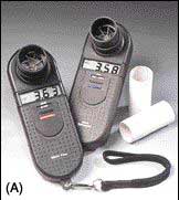
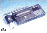
Photo 2. Shown are three different spirometers made by Micro Medical Ltd. The two units in (A) are monitoring spirometers, the Micro MS01 (right) and MicroPlus Model MS03. These handheld devices are used by clinicians in hospital emergency rooms, at the bedside, and at home by the patient for quick assessment of asthma, chronic obstructive pulmonary disease, and lung transplant patients. The MS01 measures the forced expired volume in 1 s (FEV1) and the forced vital capacity (FVC), the two measures most frequently used for determining lung function impairment. The MS03 also measures peak expiratory flow (PEF) and calculates the forced expired ratio (FEV1%), which is the ratio of FEV1 to FVC and is a quantity often used in assessing airflow obstruction. Although spirometry cannot actually provide diagnoses of specific diseases, these types of measurements can allow a clinician to assess respiratory function and differentiate between obstructive and restrictive lung dysfunctions; the characteristics of flow curves can assist clinicians further in identifying patterns of abnormality [17]. The Microlab model ML3300 desktop diagnostic spirometer in (B) comes with a bidirectional transducer and will record flow vs. volume and volume vs. time curves. It has a graphics display, printer, and full internal database for up to 90 patients. (Photos courtesy of Micro Direct, Inc.)
Various technologies are used in spirometry and respiratory flow measurement in general. The Wright respirometer, named for its inventor [16], today refers to a type of handheld monitoring spirometer that incorporates a special type of tangential turbine transducer with a two-bladed rotor connected to a mechanical pickup and a dial readout for the volume. These particular devices are routinely used by respiratory therapists for patient weaning and ventilator checking. Other true axial turbine–based flowmeters are available for ventilation measurements involving, for example, patient metabolics measurements. The current leading spirometer manufacturer is Micro Medical, Ltd., all of whose units have a removable flow transducer element that incorporates an axially mounted, flat, two-bladed rotor driven by induced swirl. The units use an IR optical pickup, have a battery-powered, microprocessor-controlled display, and are available in various monitoring and diagnostic versions (see Photo 2).
A key design aspect in modern spirometers is the range of functionalities accorded by the associated electronic processing of the transducer signals so as to be able to reliably calculate, and afterward conveniently display, relay, or record a range of the various clinical measures that are a feature of spirometry. In these medical devices, rotors tend to be plastic with a large blade radius ratio; flow conditioning is minimal or absent. The meters are typically accurate to a few percent of reading. In the U.S., spirometers are designated as class 2 medical devices, and certain FDA approvals are required concerning manufacture and marketing. In the EU they are class IIb medical devices under a different system and other approvals are required.
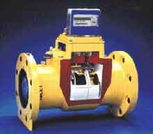 |
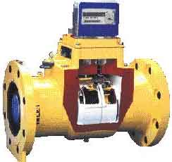
| Photo 3. The Auto-Adjust Turbine flowmeter from Equimeter, Inc., is a dual-rotor axial turbine designed specifically for accurate and reliable measurements of natural gas flows in custody transfer applications. The unit shown is the 6 in. Model AAT-35 with an ANSI 150 steel body; a cover plate has been removed to show the two turbine rotors. The blue rotor (left) is the main rotor and the yellow rotor is the sensor rotor. Errors due to inlet flow swirl, and increases in main bearing torque that may occur over time due to wear, affect the rotational speed of both rotors in a manner that allows the meter to be automatically and continuously compensated so as to maintain the calibration performance. Accuracy is ±0.2%. The top register is driven by a mechanical pickup from the main rotor. The meter shown also has blade tip sensors installed for an electronic output. (Photo courtesy of Equimeter, Inc.) |
Dual-Rotor Axial Turbines
Dual-rotor axial turbines have performance features not found in single-rotor designs. In 1981, Lee et al. [18] were issued a U.S. patent for a self-correcting, self-checking, dual-rotor turbine flowmeter that is currently manufactured exclusively by Equimeter, Inc., and sold as the Auto-Adjust Turbine. This is a high-accuracy flowmeter primarily intended for use on large natural gas lines where even small undetected flow measurement errors can be costly. Meter sizes range from 4 in. to 12 in. The design incorporates two closely coupled turbine rotors that rotate in the same direction. Photo 3 depicts an Auto-Adjust where a cover plate has been removed to show the two rotors. The upstream rotor is the main rotor and the second rotor, which has a much shallower blade angle, is the sensor rotor. Continuous and automatic correction of measurement errors due to varying bearing friction is achieved by calculating the flow rate based on the difference between the rotor speeds. As shown in Part 1, Figure 2, and discussed in the theory section, the flow exit angle is due to the net rotor retarding torque. If this torque increases in the main rotor, thereby reducing its speed, the exit angle increases and the speed of the sensor rotor is reduced as well. The meter is also insensitive to inlet swirl angle because the swirl affects both rotor speeds in the same sense and the effect is then subtracted in the flow calculation. The meter also checks itself for wear and faults by monitoring the ratio of the two rotor speeds and comparing this number with the installation value [19].
A dual-rotor liquid flowmeter, invented by Ruffner et al. [20], is now manufactured exclusively by Flowdata as the Exact Series. It is a high-accuracy device (up to ±0.15% linearity and ±0.02% repeatability), which in this case has an extraordinarily wide dynamic range of up to 700:1 with a single-viscosity liquid. Introduced a few years ago, this flowmeter had early commercial success in fuel flow measurement in large jet engine test stands where the wide dynamic range is particularly useful [21]. A gas version currently undergoing beta testing is expected to also deliver exceptionally wide dynamic range performance [22]. As shown in Photo 4 and Figure 4, the meter incorporates two closely coupled rotors that rotate in opposite directions. Due to the exit angle generated by the first rotor, the second rotor continues to rotate to much lower flow rates compared to the first.
 |
1. Unconditioned flow enters flowmeter. 2. Straightening vanes smooth the flow as it enters the first rotor. 3. Flow transfers momentum to the first rotor making it spin counterclockwise. Flow then exits rotor with a clockwise spin. 4. Flow enters second rotor with a nearly perpendicular angle of attack thereby transferring additional momentum to the second rotor. This additional momentum results in greatly extended turndown. 5. Flow exits flowmeter. 6. A pickup transmits the rotor frequency signal to remote instrumentation. Optional dual pickups transmit signals from both rotors, the sum of which is a constant for any given flow rate. This provides not only wider turndown but powerful diagnostics and turbulence insensitivity as well. |
Two-Phase Flow Measurement Using Axial Turbines
A differential pressure producing device such as a venturi meter in series with a turbine is known to be a technically appropriate and straightforward method for measuring the volumetric and mass flow rates of some fine, solid aerosols. This section, however, highlights a current research area in the application of axial rotor turbine meters to a range of industrial flow measurement problems where gas/liquid, two-phase flows are encountered. Turbine meters are not customarily designed for and cannot measure such flows accurately. Errors on the order of 10% arise in metering liquids with void fractions of ~20%. Such flows are normally measured after gas separators.
Although the problem is not restricted to these industries, the research is at present being driven by a need for direct measurement of crude oil in offshore multiphase production systems, the measurement of water/steam mixtures in the cooling loops of nuclear reactors, and the measurement of Freon liquid-vapor flows in refrigeration and air conditioning equipment. Several techniques investigated so far use an auxiliary sensor. This may be either a void fraction sensor or a pressure drop device such as a venturi meter or drag disk; the pressure drop approach appears to be technically more promising [23,24]. Furthermore, from a practical standpoint, gamma densitometers for measuring void fraction are additional and expensive equipment and not, for instance, well adapted for use in undersea oil fields.
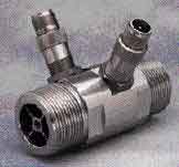 |
| Photo 4 and Figure 4. The Exact Series turbine from Flowdata is designed to accurately measure liquid flow. A dual-rotor configuration provides exceptionally high turndown ratios of up to 700:1 with a single-viscosity fluid. The meter shown here is 1-1/4 in. size and connects to a small flow computer that calculates the flow rate. The pickoffs have an optional fluid temperature sensor. The Strouhal/Roshko technique is used to correct the output for fluid viscosity variations. The rotation speeds of the two rotors vs. flow rate are also compared using proprietary algorithms. A deviation exceeding certain limits indicates that the meter is going out of calibration, and the user is alerted. (Photo courtesy of Flowdata.) |
Two techniques currently under investigation do not require an auxiliary inline sensor. The first uses the turbine meter itself as the drag body and combines the output of the turbine with that of a small differential pressure sensor connected across the inlet and outlet regions. This technique requires a homogenizer ahead of the turbine, and measurement accuracies of ±3% for the volumetric flow rates of both phases have been reported for air/water mixtures up to a void fraction of 80% [25].
The second technique is based entirely on analysis of the turbine output signal and has provided significant correlations of the signal fluctuations with void fraction. Accuracies of water volumetric flow rate measurement of ±2% have been reported when using air/water mixtures with void fractions of up to 25% [26].
Insertion Axial Turbine Flowmeters
These flowmeters comprise a small axial rotor mounted on a stem that is inserted radially through the conduit wall, often through a shutoff valve. The devices measure the flow velocity at the rotor position, from which the volumetric flow rate is inferred. An economical solution to flow measurement problems where pipe diameters are high and accuracy requirements are moderate, the meters may also be preferable where negligible pressure drop is an advantage, as in high-speed flows. They are typically more linear than insertion tangential turbine flowmeters and compete also with magnetic and vortex shedding insertion flowmeters. The meters are available for the measurement of a range of liquids and gases, including steam, similar to the media range of full-bore axial turbines, and have a similarly linear response. Flow Automation, Inc., is at present the leading manufacturer; one of the company's insertion axial turbine flowmeters suitable for high-pressure installations is shown in Photo 5.
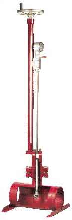 |
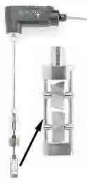
| Photo 5. The Model VR-600 insertion turbine flowmeter made by Flow Automation is designed for high-pressure flow measurements of up to 1440 psig at 100°F standard (ANSI 600). It is used to meter the flows of either gases or liquids such as natural gas, crude oil, and finished products in line sizes of 4 in. and up. The insertion travel, which in the standard format is 30 in., is hand controlled. The 2 in. dia. turbine rotor is made of stainless steel; the rotor bearings are tungsten carbide/stellite for liquid service, while shielded ball bearings are used for gas service. The unit can be fitted with an optional pressure transmitter and platinum RTD temperature sensor. Linearity is ±0.5% over a 5:1 range and ±1% over a 10:1 range, and the repeatability is 0.15%. Typical velocity ranges are 2–40 fps for liquids and 5–100 fps for gases. (Photo courtesy of Flow Automation, Inc.) |
The rotors, which are usually metal but can be plastic, typically have diameters of 25 mm to 51 mm (1–2 in.). They can be inserted into pipes with diameters ranging from 51 mm to 2032 mm (2–80 in.). Velocity measurement ranges cover 0.046 m.s–1 to 91 m.s–1 (9–18,000 fpm) for gases and 0.03 m.s–1 to 30 m.s–1 (6–6000 fpm) for liquids. Dynamic ranges vary from 10:1 to 100:1. The maximum flow rate measurement capacity in a 1836 mm (72 in.) dia. pipe can be as high as nearly 56,500 m3/hr, (~250,000 gpm). Since these devices are local velocity sensors, calculating the volumetric flow rate requires a knowledge of the area velocity profile and the actual flow area. Flow conditioning is therefore particularly important for accurate volumetric measurements. Radial positioning, a further responsibility of the user, must be in accordance with the manufacturer's recommendation, which can be centerline, 1/3 of the diameter, 12% of the diameter, or determined by "profiling."
Quick [27] discusses operation and installation for natural gas measurement. Linearities or "accuracies" may be quoted up to ±1% of velocity, but achieving the same accuracy for the volumetric flow rate, though possible, may be difficult or impractical. In this respect a unique dual-rotor design, exclusive to Onicon, Inc., and primarily used for chilled water flow measurement in HVAC systems, requires less flow conditioning than single-rotor designs. The Onicon dual-rotor insertion turbine in Photo 6 incorporates two rotors that rotate in opposite directions. The output is based on the average rotor speed. Any flow swirl present due to poor flow conditioning changes the speed of rotation of each rotor by the same but opposite amounts. Swirl-induced error is thus virtually absent in the averaged output. Also, flow profile sampling is improved over that of a single rotor. The devices are individually calibrated using a volumetric standard. The specified accuracy of ±2% of reading applies over a 50:1 velocity range of 0.4 fps to 20 fps, and improves to ±0.5% at the calibrated flow speed.
Multijet Turbine Flowmeters
These linear, volumetric flowmeters designed for liquids measurements incorporate a single radial-vaned impeller, vertically mounted on a shaft bearing within a vertically divided flow chamber, sometimes called a distributor (see Photo 7). The impeller is often plastic and may even be neutrally buoyant in water. There are various designs, but typically both chambers access a series of radially distributed and angled jets. The lower chamber jets connect to the flowmeter input port and distribute the flow tangentially onto the lower region of the impeller blades. The upper series, which is angled oppositely, allows the flow to exit. The flow pattern within the flow chamber is thus a vertical spiral, and the dynamic pressure drives the impeller to track the flow. This design gives the meters good sensitivity at low flow rates. Due to the distribution principle, the meters are also insensitive to upstream flow conditions.
 |
| Photo 6. Onicon's F1200 series dual-rotor, insertion axial turbine flowmeter is designed primarily for applications in water flow measurement in HVAC systems. The patented dual-rotor design renders the flowmeter insensitive to errors due to flow swirl. This is an important source of error in single-rotor axial turbine flowmeters, particularly where straight pipe runs are short as is often the case in HVAC installations. The flow reading is based on the average rotation speed of the two rotors. In this model, the rotation pickups are two separate electrical impedance sensors. Pickup drag is zero, and the rotors can also be made of low-inertia plastic instead of metal, factors that enhance low-flow sensitivity and response time. Because the pickup is nonmagnetic, the meter does not accumulate magnetically attracted particulates from the flow that could clog the mechanism and degrade performance. The metered medium, however, must be at least slightly electrically conductive. Each meter has a NIST traceable volumetric calibration and is accurate to ±2% of reading across a turndown ratio of 50:1 and ±0.5% at the calibrated typical velocity. (Photo courtesy of Onicon Inc.) |
Impeller rotation pickups are always mechanical, often magnetically coupled, and frequently also connect with electric contact transmitters. They are used primarily in water measurement including potable water for domestic and business billing purposes and in conjunction with energy management systems such as hot water building or district heating. They are also used, to a much lesser extent, in some chemical and pharmaceutical industries for dosing and filling systems involving solvents, refrigerants, acids, and alkalis with absolute viscosities <4.5 mPa.s, (0.045 Poise). Sizes range from 15 mm to 50 mm. Dynamic ranges lie between 25:1 and 130:1. Flow measurement ranges cover 0.03–30 m3/hr (0.13–
130 gpm). Measurement linearities range from ±1% to ±2%, with typical repeatabilities of ±0.3%. Operating temperatures are from normal to 90°C (200°F), and maximum operating pressures are available up to 6.9 MPa (1000 psi).
A number of potable water measurement systems come with sophisticated telemetry options that allow remote interrogation by radio or telephone. For potable water applications in the U.S., these meters normally comply with the applicable AWWA standard [28]; in Europe, EEC, DIN, and other national standards apply.
There is also another type of vaned flowmeter that could in principle be considered a type of multijet turbine. This type comprises an axially mounted impeller with two or more flat blades and an upstream element that imparts a helical swirl to the flow. Specialized applications are found in the pharmaceutical, medical, and beverage industries. Although most commonly used for liquids measurements, this type is also suitable for gas measurements (although at a lower accuracy) and is, for instance, the design used in all the Micro Medical spirometers described earlier. The transducer is typically a small, low-cost, sometimes disposable, plastic component capable of measuring low flow rates, (down to 50 ml/min.). The dynamic range is typically high and accuracies range up to ±0.5%. Goss [29] describes one particular design in current use.
Conclusion
However anachronistic that intricate mechanical sensors may appear in the light of today's high technology, there are fundamental reasons axial turbines are likely to experience continued support and development rather than face obsolescence. This is especially true for inline applications requiring in the region of tenth percent volumetric accuracy. Mechanical coupling is the most direct volume interaction for a flowing fluid, which is why mechanical meters historically developed first and continue to be among the most accurate and reliable types of flowmeters for so many different fluids.
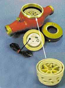 |
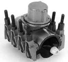
| Photo 7. The Model 1742 multijet turbine flowmeter made by ABB Kent Messtechnik GmbH is a 1.5 in. size. The top counter housing has been removed to reveal the turbine assembly. In the lower right photo of the distributor/impeller assembly can be seen the two circumferential rows of multiple jet orifices, where the entrance angle of the top row (outlet) opposes that of the bottom row (inlet). The outside surface ledge seals against an internal flange in the brass housing so that all the flow passes through the jets and hence the distribution chamber. The mechanical rotor shaft pickup is magnetically coupled to the counter gear housing. This particular unit also has an optional pulse output. Applications include metering potable water, hot and cold water in steam and hydronic heating systems, well water, contaminated water in ground water remediation, and irrigation water for golf courses. Typical linearity is ±2% of reading over 0.8 gpm to 90 gpm. (Photos courtesy of ISTEC Corp.) |
The technology of high-accuracy flowmeters continues to be driven by applications such as the custody transfer of valuable oil and natural gas, which demand high accuracy and reliability. There is a continuing requirement for accurate and reliable water flowmeters. By reason of long-proven field experience, turbine and other vane-type devices have become one of a few broadly accepted techniques in many major applications where the demand for flow sensors is significant or growing.
References
14. AWWA C704-92. 1992. Propeller-type meters for waterworks applications, Denver, CO, Amer. Water Works Assoc.
15. ANSI/AWWA C701-88. 1988. Cold water meters--turbine type, for customer service, Denver, CO, Amer. Water Works Assoc.
16. B.M. Wright and C.B. McKerrow. 1959. "Maximum forced expiratory flow rate as a measure of ventilatory capacity," Brit Med J:1041-1047.
17. C.G. Bosse and G.J. Criner. 1993. "Using spirometry in the primary care office. A guide to technique and interpretation of results," Postgrad Med, 93 (5):122-4, 129-30, 133-6.
18. W.F.Z. Lee, R.V. White, F.M. Sciulli, and A. Charwat. 1981. Self-correcting, self-checking turbine meter, U.S. Patent 4,305,281.
19. W.F.Z. Lee, D.C. Blakeslee, and R.V. White. 1982. "A self-correcting and self-checking gas turbine meter," Trans ASME, J Fluids Eng, 104:143-149.
20. D.F. Ruffner and P.D. Olivier. 1997. Wide range, high accuracy flow meter, U.S. Patent 5,689,071.
21. D.F. Ruffner. 1996. Private communication.
22. C.D. Foran. 1999. Private communication.
23. A. Abdul-Razzak, M. Shoukri, and J.S. Chang. 1995. "Measurement of two-phase refrigerant liquid-vapor mass flow rate--part III: combined turbine and venturi meters and comparison with other methods," ASHRAE Trans: Research 101 (2):532-538.
24. W.J. Shim, T.J. Dougherty, and H.Y. Cheh. 1996. "Turbine meter response in two-phase flows," Proc Int Conf Nucl Eng--4, 1 part B:943-953 (New York, NY:ASME).
25. K. Minemura, K. Egashira, K. Ihara, H. Furuta, and K. Yamamoto. 1996. "Simultaneous measuring method for both volumetric flow rates of air-water mixture using a turbine flowmeter," Trans ASME, J Energy Resources Technol, 118:29-35.
26. M.W. Johnson and S. Farroll. 1995. "Development of a turbine meter for two-phase flow measurement in vertical pipes," Flow Meas Instrum, 6 (4):279-282.
27. L.A. Quick. 1995. "Gas measurement by insertion turbine meter," Proc 70th Int School Hydrocarbon Meas, OK. (Available E. Blanchard, Arrangements Chair, Shreveport, LA, 318-868-0603.)
28. ANSI/AWWA C708-91. 1991. Cold-water meters, multi-jet-type, Denver, CO, Amer. Water Works Assoc.
29. J. Goss. 1994. Flow meter, U.S. Patent 5,337,615.
30. C.R. Sparks. 1996. Private communication.
For Further Reading
ATS Standardization of spirometry. 1994 Update. Amer J Respir Crit Care Med 152:1107-1136, 1995. The latest version of the official U.S. guideline for spirometry, generated by the American Thoracic Society.
DeFeo, J.W. 1992. "Turbine flowmeters for measuring cryogenic liquids," Adv Instrum Proc, 47 pt.1:465-472, ISA, provides guidance for a less frequently discussed application in which axial turbines perform well.
Jungowski, W.M. and M.H. Weiss. 1996. "Effects of flow pulsation on a single-rotor turbine meter," Trans ASME, J Fluids Eng, 118 (1):198-201.
Lebowitz, M.D. 1991. "The use of expiratory flow rate measurements in respiratory disease," Ped Pulmonology, 11:166-174. Provides a review of the diagnostic usefulness of PEFR using portable spirometers.
Lui, J. and B. Huan. 1995. "Turbine meter for the measurement of bulk solids flowrate, Powder Technol 82:145-151. Describes theory and experiments relating to a very simple design for a unique application, namely the volumetric measurement of plug flows of sands in a pipe.
Nicholl, A.J. 1977. "Factors affecting the performance of turbine meters," Brown Boveri Rev, 64 (11): 684-692. Describes some basic design factors not commonly discussed elsewhere.
Ogawa, K., S. Ito, and C. Kuroda. 1990. "Laminar-turbulent velocity profile transition for flows in concentric annuli, parallel plates and pipes," J Chem Eng Japan, 13 (3):183-188. Provides mathematical descriptions of velocity profiles.
Sparks, C.R. and R.J. McKee. 1996. Method and apparatus for assessing and quantifying pulsation induced error in gas turbine flow meters, U.S. Patent 5,481,924. Assigned to the Gas Research Institute, Chicago, this is a potential solution to the accurate measurement of pulsating gas flows that will require engineering development and a high-performance rotation sensor [30].
Spitzer, D.W. (Ed.). 1991. Flow Measurement, Research Triangle Park, NC: ISA. A popular 646-page practical engineering guide, four chapters of which address turbine flowmeters, sanitary flowmeters, insertion flowmeters, and custody transfer issues.
This article is adapted from D. Wadlow, "Turbine and vane flowmeters," The Measurement, Instrumentation and Sensors Handbook, Chapter 28.4, J.G. Webster, Ed., Boca Raton, FL: CRC Press, LLC, Dec. 1998, and is excerpted by permission of CRC Press.
 | ABB Kent Messtechnik GmbH Otto-Han-Strasse 25 D-68623 Lampertheim Germany | Micro Medical Ltd. PO Box 6 Rochester Kent ME1 2AZ U.K. |
| ISTEC Corp. (U.S. Distributor) 415 Hope Ave. Roselle, NJ 07203 908-241-8880 Fax 908-241-7288 [email protected] www.istec-corp.com | Micro Direct, Inc. (U.S. Distributor) 803 Webster St. Lewiston, ME 04240 800-588-3381 Fax 207-786-7280 [email protected] www.micro-direct.com | |
| Equimeter, Inc. 805 Liberty Blvd. PO Box 528 DuBois, PA 15801 800-375-8875 Fax 814-375-8460 www.equimeter.com | Onicon Inc. 2161 Logan St. Clearwater, FL 33765 727-447-6140 Fax 727-442-5699 [email protected] | |
| Flow Automation Inc. 9303 W. Sam Houston Pkwy. South Houston, TX 77099-5298 713-272-0404 Fax 713-272-2272 www.flowautomation.com | Sensus Technologies, Inc. 450 N. Gallatin Ave. Uniontown, PA 15401-2494 800-638-3748 Fax 724-439-7729 [email protected] www.sensus.com | |
| Flowdata 1817 Firman Dr. Richardson, TX 75081 800-833-2448 or 972-907-2787 Fax 972-907-8016 www.flowdata.com | ddd | |