
The modern axial turbine flowmeter, when properly installed and calibrated, is a reliable device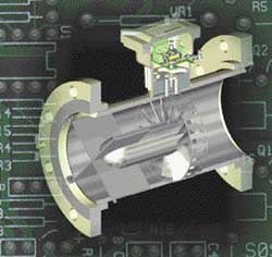 capable of providing the highest accuracies attainable by a commercially available flow sensor for both liquid and gas volumetric flow measurement. These devices are the result of decades of intensive innovation and refinements to the original axial vaned flowmeter principle first credited to Woltman in 1790, and applied at that time to measuring water flow. Modern development activity was largely driven by the U.S. natural gas industry, which in the late 1940s and 1950s needed a way to accurately measure the flow in large-diameter, high-pressure, interstate natural gas lines. Today, axial turbine flowmeters of differing and often proprietary designs are used for a variety of applications where accuracy, reliability, and rangeability are required in numerous major industries including water, natural gas, oil, petrochemical, chemical process, cryogenics, milk and beverage, aerospace, and biomedical.
 |
| Figure 1. The key components of an axial turbine flowmeter can be seen in this longitudinal section view. The flowmeter body is usually a magnetically transparent stainless steel such as 304. Common end-fittings include face flanges (shown), various threaded fittings, and Tri-Clover fittings. The upstream and downstream diffusers are the same in bidirectional meters and are generally supported by three or more flat plates or sometimes tubular structures, aligned with the body, that also act as flow straighteners. The relative size of the annular flow passage at the rotor varies among different designs. Journal rotor bearings are frequently used for liquids, while ball bearings are often used for gases. Magnetic reluctance pickups (shown) are frequently used. Other types include mechanical and modulated- carrier pickups. (Courtesy of CRC Press, LLC.) |
Figure 1 is a schematic longitudinal section through the axis of symmetry showing the key components of a typical meter. The meter is an inline sensor that incorporates a single turbine rotor concentrically mounted on a shaft within a cylindrical housing through which the flow passes. The shaft or shaft bearings are located by end supports inside suspended upstream and downstream aerodynamic structures called diffusers, stators, or simply cones. The flow thus passes through an annular region occupied by the rotor blades. The blades, which are usually flat but may be slightly twisted, are inclined at an angle to the incident flow velocity and hence experience a torque that drives the rotor. The rate of rotation, which can be up to several tens of thousands of rpm for smaller meters, is detected by a pickup, usually a magnetic type, and registration of each rotor blade passing implies the passage of a fixed volume of fluid.
General Performance Characteristics
Axial turbines perform best when measuring clean, conditioned, steady flows of gases and liquids with low kinematic viscosities (below about 10–5 m2s–1,or 10 cSt, although they are used up to 10–4 m2s–1, or 100 cSt), and are linear for subsonic, turbulent flows. Under these conditions the inherent mechanical stability of the meter design provides excellent repeatability. Except for the special case of water meters, which are described later, the main performance characteristics are:
- Sizes (i.d.): 6–760 mm (1/4–30 in.)
- Maximum measurement capacities: 0.025–25,500 Am3/hr (0.015–15,000 ACFM) for gases, where A denotes actual; 0.036–13,000 m3/hr (0.16–57,000 gpm or 82,000 barrels/hr) for liquids
- Typical repeatability: ±0.1% of reading for liquids; ±0.25% for gases, with up to ±0.02% for high-accuracy meters
- Typical linearities (before electronic linearization): 0.25% to ±0.5% of reading for liquids; ±0.5% to ±1.0% for gases. (High-accuracy meters have linearities of ±0.15% for liquids and ±0.25% for gases, usually specified over a 10:1 dynamic range below maximum rated flow. Traceability to NIST is frequently available, allowing the estimation of a flowmeter's overall absolute accuracy under specified conditions. Under ideal conditions, absolute accuracies for optimum designs and installations can approach the accuracy capabilities at NIST, which are stated as ±0.13% for liquid flows and ±0.25% for air.)
- Rangeability, when defined as the ratio of flow rates over which the linearity specification applies: typically between 10:1 and 100:1
- Operating temperature ranges: –270°C to 650°C (–450°F to 1200°F)
- Operating pressure ranges: from coarse vacuum to 414 MPa (60,000 psi)
- Pressure drop at the maximum rated flow rate: ~0.3 kPa (0.05 psi) for gases;
~70 kPa (10 psi) for liquids
Theory
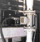 |
| The Brooks turbine flowmeter from Daniel Measurement and Control shown here features the UMB (universal mounting box). Designed for oil custody transfer operations, the unit can be provided with either a single or a dual pickoff (dual for higher resolution). The UMB offers the advantage of a single enclosure for both dual and single pickoffs. (Photo courtesy of Daniel Measurement and Control.) |
The current literature discusses two techniques for analyzing axial turbine performance. The first describes the fluid driving torque in terms of momentum exchange; the second describes it in terms of aerodynamic lift via airfoil theory. The advantage of the former technique is that it readily produces analytical results describing basic operation, some of which have not appeared via airfoil analysis. Although the latter approach allows more complete descriptions using fewer approximations, it is mathematically intensive and leads rapidly into computer-generated solutions. One prominent pioneer of the momentum approach is Lee [1] who went on to invent one of the few currently successful dual-rotor turbine flowmeters. Thompson and Grey [2] provided one of the most comprehensive models based on the airfoil technique, taking into account, for instance, the effects of blade interference. The following discussion uses the momentum exchange approach as a way to highlight the basic concepts of the axial turbine flowmeter.
In a hypothetical situation, where there are no forces acting to slow down the rotor, it will rotate at a speed that exactly maintains the fluid flow velocity vector at the blade surfaces. Figure 2 is a vector diagram for a flat-bladed rotor with a blade pitch angle equal to ![]() . Assuming that the rotor blades are flat and that the velocity is everywhere uniform and parallel to the rotor axis, then referring to Figure 2:
. Assuming that the rotor blades are flat and that the velocity is everywhere uniform and parallel to the rotor axis, then referring to Figure 2:
Eliminating the time dimension from the left-hand side quantity reduces it to the number of rotor rotations per unit fluid volume, which is essentially the flowmeter K factor specified by most manufacturers. Hence, according to Equation (2), in the ideal situation the meter response is perfectly linear and determined only by geometry. (In some flowmeter designs the rotor blades are helically twisted to improve efficiency. This is especially true of blades with large radius ratios, R/a. If the flow velocity profile is assumed to be flat, then the blade angle in this case may be described by tanb = constant 3 r. This is sometimes called the "ideal" helical blade.) In practice, there are instead a number of rotor retarding torques of varying relative magnitudes. Under steady flow, the rotor assumes a speed that satisfies the following equilibrium:
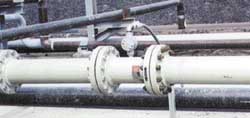 |
| This 8 in., 600 lb. Brooks Parity turbine flowmeter from Fisher-Rosemount Petroleum is a volumetric flow measurement and transmitting device used extensively in the petroleum industry. Among its features are an output linear with flow rate; a bidirectional flow option; horizontal or vertical installation; and field-mountable pickoffs that require no interruption of conduit lines. Linearity is ±0.15% and repeatability is ±0.02%. Optional temperature ratings of –40°F to 400°F (–40°C to 204°C) and –350°F to 400°F (–212°C to 204°C) are available. (Photo courtesy of Fisher-Rosemount Petroleum.) |
fluid driving torque
= rotor blade surfaces' fluid drag torque
+ rotor hub and tip clearance fluid drag torque
+ rotation sensor drag torque
+ bearing friction retarding torque (3)
Referring again to Figure 2, the difference between the actual rotor speed, r![]() , and the ideal rotor speed, r
, and the ideal rotor speed, r![]() i, is the rotor slip velocity due to the combined effect of all the rotor retarding torques as described in Equation (3). As a result, the fluid velocity vector is deflected through an exit or swirl angle,
i, is the rotor slip velocity due to the combined effect of all the rotor retarding torques as described in Equation (3). As a result, the fluid velocity vector is deflected through an exit or swirl angle,![]() . Denoting the radius variable by r, and equating the total rate of change of angular momentum of the fluid passing through the rotor to the retarding torque, one obtains:
. Denoting the radius variable by r, and equating the total rate of change of angular momentum of the fluid passing through the rotor to the retarding torque, one obtains:
 |
| Figure 2. As shown in this vector diagram for a flat-bladed axial turbine rotor, the difference between the ideal ( |
The trends evident in Equation (6) reflect the characteristic decline in meter response at very low flows and the reason that lower friction bearings and lower drag pickups tend to be used in gas rather than liquid applications and small-diameter meters. In most flowmeter designs, especially those for liquids, the latter three of the four retarding torques described in Equation (3) are small under normal operating conditions compared to the torque due to induced drag across the blade surfaces. As shown in Figure 2, the force, F, due to this effect acts in a direction along the blade surface and has a magnitude given by:
where:
CD = drag coefficient
S = blade surface area per side
Using the expression for drag coefficient corresponding to turbulent flow selected by Pate et al. [3] and others, this force may be estimated by:
![]()
where:
Re = flow Reynolds number based on the blade chord shown as dimension c in Figure 2. Assuming ![]() is small compared with
is small compared with ![]() , after integration the magnitude of the retarding torque due to the induced drag along the blade surfaces of a rotor with n blades is found to be:
, after integration the magnitude of the retarding torque due to the induced drag along the blade surfaces of a rotor with n blades is found to be:
![]()
Combining Equations (9) and (6), and rearranging yields:
![]()
 |
| Figure 3. A typical single-rotor axial turbine linearity error, or calibration, curve is plotted for a low-viscosity fluid showing the principal alternative presentations in current use. Higher accuracy specifications usually correspond to a 10:1 flow range down from Qmax, while extended operating ranges usually correspond to reduced accuracies. The hump in the curve is a characteristic feature caused by flow velocity profile changes as Re approaches the laminar region. This feature varies in magnitude from one meter to the next. Sensitivity and repeatability degrade at low Re. Percent registration is used only with meters that have mechanical pickups. All other meters have a K factor. UVC and Re calibrations remain in effect at different known media viscosities, provided Re or f/n stays within the specified range. Re is referenced to the connecting conduit diameter and is less within the flowmeter. The Re range shown is therefore approximate and can vary by an order of magnitude depending on the meter. Linearity error may also be expressed in terms of Strouhal number (fD/V) vs. Re (VD/v) or Roshko number (fD2/v), when instead D is a flowmeter reference diameter [4]. (Courtesy of CRC Press, LLC.) |
Equation (10) is an approximate expression for K factor because it neglects the effects of several of the rotor retarding torques as well as a number of meter design and aerodynamic factors such as rotor solidity and flow velocity profile. Nevertheless, it reveals that linearity variations under normal, specified operating conditions are a function of certain basic geometric factors and Reynolds number. These results reflect general trends that influence design and calibration. Additionally, the marked departure from an approximate ![]() V2 (actually
V2 (actually ![]() 0.8V1.8µ–0.2 via Re in Equation [8]) dependence of the fluid drag retarding torque on flow properties under turbulent flow, to other relationships under transitional and laminar flow, gives rise to major variations in the K factor vs. flow rate and media properties for low-flow Reynolds numbers. This is the key reason why axial turbine flowmeters are generally recommended for turbulent flow measurement.
0.8V1.8µ–0.2 via Re in Equation [8]) dependence of the fluid drag retarding torque on flow properties under turbulent flow, to other relationships under transitional and laminar flow, gives rise to major variations in the K factor vs. flow rate and media properties for low-flow Reynolds numbers. This is the key reason why axial turbine flowmeters are generally recommended for turbulent flow measurement.
Calibration, Installation, and Maintenance
Axial turbine flowmeters have a working dynamic range of at least 10:1 over which the linearity is specified. The maximum flow rate is determined by design factors related to size vs. maximum pressure drop and maximum rotor speed. The minimum of the range is determined by the linearity specification itself. Due to small, unavoidable, manufacturing variances, linearity error curves are unique to individual meters and are normally provided by the manufacturer. Although recommended where possible, however, the conditions of the application cannot usually and need not necessarily duplicate those of the initial or even subsequent calibrations. This has pivotal importance in applications where actual operating conditions are extreme or where the medium is expensive or difficult to handle. Figure 3 shows a typically shaped calibration curve of linearity vs. flow rate expressed in terms of multiple alternative measures, various combinations of which are in current use. The vertical axis thus represents one of the following: the linearity error as a percentage of flow rate, a K factor expressed in terms of the number of pulses from the rotation sensor output per volume of fluid, or the deviation from 100% registration, the latter applying only to flowmeters with mechanical pickups. The horizontal axis may be expressed in terms of flow rate in volume units/time, Reynolds number, or pulse frequency (from the rotation sensor for nonmechanical) divided by kinematic viscosity, (f/![]() ), in units of Hz per m2s–1, (Hz/cSt or Hz/SSU; 10–6 m2s–1 = 1 cSt
), in units of Hz per m2s–1, (Hz/cSt or Hz/SSU; 10–6 m2s–1 = 1 cSt ![]() 31.0 s Saybolt Universal), and where kinematic viscosity is the ratio of absolute viscosity (m) to density. Calibrations are preferably expressed, vs. Re or f/
31.0 s Saybolt Universal), and where kinematic viscosity is the ratio of absolute viscosity (m) to density. Calibrations are preferably expressed, vs. Re or f/![]() , which is proportional to Re.
, which is proportional to Re. 
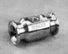
The FMC Invalco line of turbine flowmeters includes the WS series of sanitary units, designed for metering pharmaceuticals, milk, and other beverages. Among the features of the WSP5 flowmeter shown here are an electropolished super passivated rotor and support that help ensure clean flow conditions. Rulon bearings provide long service life in nonlubricating sanitary applications. The meter has the standard Tri-Clover end fittings, and in the cutaway view can be seen flush holes for the bearings to satisfy 3-A sanitary crack and crevice standards. Available sizes are 1/2–3 in.; flow rates are 1.5–600 gpm; and accuracy is better than ±0.5%. (Photo and figure courtesy of FMC Invalco.)
The hump shown in the curve is a characteristic frequently observed at lower Re and is due to velocity profile effects. K factor vs. f/![]() calibration curves are specifically called universal viscosity curves (UVC), and for most meters are available from the manufacturer for an extra charge. A key utility of UVC is that where media type and properties differ significantly from those of the original calibration, accuracies much greater than the overall linearity error can still readily be obtained via the flowmeter's UVC if the kinematic viscosity of the application is known. An alternative, advanced calibration technique [4] is to provide response in terms of Strouhal number vs. Re or Roshko number. This approach, although not widely used, is gaining acceptance in certain applications [5], and it is particularly relevant to high accuracy and extreme temperature applications because it further allows correct compensation for flowmeter thermal expansion errors.
calibration curves are specifically called universal viscosity curves (UVC), and for most meters are available from the manufacturer for an extra charge. A key utility of UVC is that where media type and properties differ significantly from those of the original calibration, accuracies much greater than the overall linearity error can still readily be obtained via the flowmeter's UVC if the kinematic viscosity of the application is known. An alternative, advanced calibration technique [4] is to provide response in terms of Strouhal number vs. Re or Roshko number. This approach, although not widely used, is gaining acceptance in certain applications [5], and it is particularly relevant to high accuracy and extreme temperature applications because it further allows correct compensation for flowmeter thermal expansion errors.
The accuracy of axial turbine flowmeters is reduced by unconditioned flow, especially swirl. An installation incorporating flow conditioners along with specific upstream and downstream straight pipe lengths is generally recommended [6]. Some axial turbine flowmeters can be purchased with additional large flow straighteners that mount directly ahead of the flowmeter body with or conditioning plates that are integral to the body. The manufacturer is the first source of information regarding installation.
Errors due to flow velocity pulsations are another concern, particularly in certain gas installations, but no standard technique for effectively counteracting this source of error has yet been adopted. Periodic maintenance, testing, and recalibration is required because the calibration will shift over time due to wear, damage, or contamination. For certain applications, especially those involving custody transfer of oil and natural gas, national and international standards and other recommendations exist that specify the minimum requirements for turbine meters with respect to these aspects, [7,8,9,10,11].
Design and Construction
The many, often proprietary, flowmeter designs incorporate variations in rotors, bearings, pickups, and other components in formats and materials that are tailored to different applications. Meter bodies are available with a wide range of standard end-fittings. Within application constraints, the primary objective is usually to optimize the overall mechanical stability and fit in order to achieve good repeatability. Performance, application, and manufacturing considerations affect every internal component, but most of all the rotor with respect to blade shape and pitch, blade count, and balance and rigidity vs. drag, stress, and inertia; bearings with respect to precision vs. friction, speed rating, and durability; and rotation pickup vs. performance and drag.
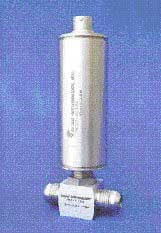 |
| Flow Technology's FT6-8AEU2-LEA-0 flowmeter, electronics model number SIL-3-C-V-1, has a range of 0.5–5 gpm. When combined with the Smart Integral Linearizer (SIL), it has the capability of real-time compensation for variations in viscosity and density due to temperature changes. Integrating the temperature measurement into the flowmeter/electronics package allows the SIL to directly output a corrected signal. This meter is equipped with MilSpec flared end fittings and is designed for aerospace applications. The 1/2 in. size shown here would be suitable as part of the fuel management system for a helicopter. (Photo courtesy of Flow Technology, Inc.) |
Most low-radius-ratio blades are machined flat, while high-ratio blades tend to be twisted. The blade count varies from about 6 to 20 or more depending on the pitch angle and blade radius ratio so that the required rotor solidity is achieved. Rotor solidity is a measure of the "openness" to the flow such that higher solidity rotors are more highly coupled to the flow and achieve a better dynamic range. The pitch angle, which primarily determines the rotor speed, is typically 30°–45° but may be lower in flowmeters designed for low-density gas applications. Rotor assemblies are usually a close fit to the inside of the housing. In large-diameter meters the rotor often incorporates a shroud around the outer perimeter for enhanced stability. Also, since large meters are often used for heavy petroleum products, the fluid drag created by the wall clearance gap is often designed to offset the tendency at high media viscosities for the meter to speed up at lower Reynolds numbers. The materials of construction range from nonmagnetic to magnetic steels to plastics.
Stainless steel ball bearings tend to be used for gas meters and low-lubricity liquids such as cryogenic liquids and freon; combination tungsten carbide or ceramic journal and thrust bearings are often considered best for many other liquid meters depending on the lubricity of the medium. Fluid bearings (sometimes called "bearingless" designs) are often used in conjunction with the latter, but sometimes with gases as well, for reducing the drag. They operate by various designs that use flow-induced forces to balance the rotor away from the shaft ends. Bearing lubrication is either derived from the metered medium, or an internal or external system is provided. The more fragile, jeweled pivot bearings are also used in certain gas applications and small meters. Sanitary meters may incorporate flush holes in the bearing assembly to meet 3A crack and crevice standards.
The most common types of rotation sensor are magnetic, modulated carrier, and mechanical, but optical, capacitive, and electrical resistance are also used. In research, a modulated nuclear radiation flux rotation sensor for use in certain nuclear reactors has also been reported [12,13].
Mechanical pickups, which sometimes incorporate a magnetic coupling, are traditional in some applications. They can have high resolution and offer the advantage of requiring no electrical power, but the pickup drag tends to be high. The magnetic and modulated carrier types incorporate at least a coil in a pickup assembly that screws into the meter housing near the rotor.
In magnetic inductance types, which are now less common, the shroud or blades carry magnetized inserts and signals are induced in the coil by the traversing magnetic fields. In the more prevalent magnetic reluctance type shown in Figure 1, the coil is wrapped around a permanent magnet or magnet pole piece in the pickup assembly, which is mounted next to a high-magnetic- permeability bladed rotor (or machined shroud). The latter is then typically made of a magnetic grade of stainless steel such as 416, 430 or 17-4Ph. As the rotor turns, the reluctance of the magnetic circuit varies, producing signals at the coil. In the more expensive modulated carrier types, the rotor need only be electrically conductive. The coil is part of an RF oscillator circuit and the proximity of the rotor blades changes the circuit impedance, giving rise to modulation at a lower frequency that is recovered. The RF types have much lower drag and higher signal levels at low flow, and can operate at temperatures above the Curie point of typical ferromagnetic materials. They are preferred for wide dynamic range and high-temperature applications. Bidirectional flowmeters usually have two magnetic pickups to determine flow direction. This configuration is useful, for example, for monitoring the container filling and emptying operations often encountered in sanitary applications. Multiple magnetic pickups are also used in some designs to provide increased measurement resolution. As for output, various pulse amplifiers, totalizers, and flow computers for gas pressure and temperature correction, along with 4–20 mA and other standard interface protocols, are available to suit particular applications. As an example of advanced transmitters, at least one manufacturer (Flow Technology, Inc., Phoenix, Arizona) provides a real-time, miniature, reprogrammable, smart transmitter that is integrated into the pickup housing along with a meter body temperature sensor, for full viscosity compensation and UVC linearization. These transmitters are designed for use in dedicated applications such as airborne fuel management, where the medium viscosity-temperature relationship is known.
References
1. W.F.Z. Lee and H.J. Evans. 1965. "Density effect and Reynolds number effect on gas turbine flowmeters," Trans ASME, J Basic Eng, 87 (4):1043-1057.
2. R.E. Thompson and J. Grey. 1970. "Turbine flowmeter performance model, Trans ASME, J Basic Eng, 92 (4):712-723.
3. M.B. Pate et al. 1984. "A computer simulation of the turbine flow meter rotor as a drag body," Proc ASME Intl Comput in Eng Conf and Exhibition, Las Vegas:184-191.
4. P.D. Olivier and D. Ruffner. 1992. "Improved turbine meter accuracy by utilization of dimensionless data," Proc 1992 Natl Conf Standards Labs (NCSL) Workshop and Symp:595-607.
5. SAE Recommended Aerospace Practice #ARP4990, 1997-09, Section 7.2.
6. ISA-RP 31.1. 1977. "Specification, installation and calibration of turbine flowmeters," Research Triangle Park, NC.
7. ANSI/ASME MFC-4M-1986 (R1990). Measurement of gas flow by turbine meters, New York, NY.
8. API MPM. 1995. "Measurement of liquid hydrocarbons by turbine meters," 3rd Ed., Washington, DC: American Petroleum Inst.
9. AGA Transmission Meas. Committee Rep. No. 7. 1981. "Measurement of fuel gas by turbine meters," Arlington, VA: American Gas Association.
10. Int. Recommendation R32. 1989. "Rotary piston gas meters and turbine gas meters, Paris: International Organization of Legal Metrology.
11. ISO 9951. 1993. "Measurement of gas flow in closed conduits--turbine meters," Geneva, International Organization for Standardization (also available ANSI).
12. T.H.J.J. Van Der Hagen. 1993. "Proof of principle of a nuclear turbine flowmeter," Nucl Technol, 102 (2):167-176.
13. K. Termaat et al. 1995. Nuclear turbine coolant flow meter, U.S. Patent 5,425,064.
This article is adapted from D. Wadlow, "Turbine and vane flowmeters," The Measurement, Instrumentation and Sensors Handbook, Chapter 28.4, J.G. Webster, Ed., Boca Raton, FL: CRC Press, LLC, Dec. 1998, and is excerpted by permission of CRC Press.
Part 2 will take up dual-rotor axial turbine designs, propeller meters, spirometers, insertion axial turbines, and multi-jet turbines, and will include a description of two-phase flow measurement using axial turbines.
| Product Information |
| Tony Lupold Daniel Measurement and Control 9720 Old Katy Rd. PO Box 19097 Houston, TX 77055 713-827-3373 Fax 713-827-4360 [email protected] |
| Tony Lupold Fisher-Rosemount Petroleum* 9720 Old Katy Rd. PO Box 19097 Houston, TX 77055 713-827-3373 Fax 713-827-4360 [email protected] |
| Rex Mann Flow Technology, Inc. 4250 E. Broadway Rd. Phoenix, AZ 85040-8806 800-528-4225 or 602-437-1315 Fax 602-437-4459 [email protected] |
| FMC Invalco 2825 W. Washington PO Box 1377 Stephenville, TX 76401 800-468-2526 or 254-968-2181 Fax 254-968-5709 [email protected] |
| *Fisher-Rosemount Petroleum has merged with Daniel Industries, Inc |