
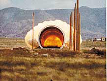
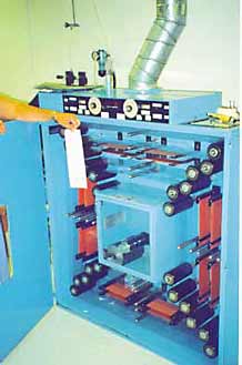
 | Photo 1. In this shock tube, the total impulse and the pressure-time history associated with an atmospheric nuclear blast are simulated. Accelerometers measure the structural response of test items placed in the mouth of the tube. |
With the end of the Cold War, the military's interest in acceleration measurements to support nuclear effects testing has waned. A corresponding decrease in shock tube (see Photo 1) and flyer plate tests has occurred, and the U.S. has ceased underground testing of nuclear devices. At the same time, more attention is being paid to acceleration measurements for pyroshock testing of military and aerospace components, a result of improved procedures based on resonant fixtures. Accelerometers have also found real-time applications in controlling and monitoring military and aerospace systems. Smart weapon systems (e.g., direct and indirect fire; and aviation-launched and ship-launched missiles, rockets, projectiles, and submunitions) are among these applications. Smart accelerometers are also being developed to support numerous military and aerospace applications. For this article, trends in cost, size, frequency response, range, reliability, and integral electronics are summarized over the 10-year span of 19891999 (see Figure 1).
 |
Figure 1. Trends in accelerometer requirments for military and aerospace applications affect price, size, frequency response, range, reliability, and integral electronics of the devices.
Lower Cost, Smaller Size
Figure 2 illustrates the historic design cycle for military and aerospace systems. A design was initiated and various alternatives were investigated with the aid of analysis tools. Instrumented design prototypes were then subjected to test and evaluation. Depending on results, the design was either qualified, or was modified, and subjected to additional testing until satisfactory results were achieved. System testing ordinarily involved more than 10 but fewer than 100 accelerometer (sensor) channels. Accelerometer measurements were typically used for structural model verification or to develop shock-test specifications for critical system components based on shock spectra [1]. A component test program could then ensure system reliability over the life of the program. Because of the limited number of measurements, the high cost of the system under test, and the reliability required, the cost of the accelerometers was seldom a consideration.
Figure 2. The conventional design cycle for military and aerospace devices entailed design, analysis, testing and evaluation, and either qualification or modification phases. Sensing technology was used only during test and evaluation.
 | Photo 2. Chemically machined MEMS accelerometer elements incorporate diffused resistive gauges and are metalized to complete their integral Wheatstone bridge. The elements are later placed in individual accelerometer housings. |
Figure 3 represents a more current version of this design cycle. Design and analysis times have been greatly compressed by virtue of the engineering tools available on PCs and workstations. Product and process are developed simultaneously. Accelerometers are used not only for system test and
| Figure 3. A more streamlined version of the design cycle shown in Figure 2 features a shortened design and analysis step followed by control/monitoring and test and evaluation, both of which are facilitated by the use of sensors. The shortened design and analysis steps are due in part to the engineering tools available on today's PCs and workstations. |  |
evaluation, but often perform control and monitoring functions as permanent parts of the system. This raises the number required from the 10100 range to thousands over the life of the program, and their cost now becomes a factor. Examples can be found in weapon-fusing functions including target discrimination, engine vibration levels on transport aircraft (operating at 1200ºF), machinery monitoring on submarines, and many other activities. Also in progress is the integration of accelerometers into inertial measuring units, where they serve to guide small munitions to a target [2].
 | Photo 3. In a continuous casting operation, ferroelectric ceramic materials are subsequently fired and poled to give them piezoelectric properties. They can be manufactured into a variety of bimorph transduction elements for integration into accelerometers. |
With these evolving applications, accelerometer manufacturers are competing with one another on the bases of performance and cost. MEMS (microelectromechanical systems) technology has found its principal application in sensor technology (see Photo 2, page 46), but the majority of military and aerospace applications are still too unique to be satisfied by the very low cost MEMS automobile air bag type of accelerometers. At present, a business area is developing that will fill in the gap between the low-volume, higher cost, test-and-evaluation market and the high-volume, very low cost MEMS commercial market.
Piezoelectric accelerometers also are being produced at lower cost for volume applications. Photo 3 shows part of a tape cast manufacturing process that enables large-scale production of ceramic transduction elements. The resultant ceramic can be made into a bimorph (sandwich-type element) for integration into accelerometers. Such devices can provide usable frequency response to several thousand hertz. High-volume costs in real dollars can be reduced by more than an order of magnitude from those of 10 years ago.
Packaging is another path toward cost reduction. An accelerometer designed for test and evaluation applications is placed in a housing that allows it to be attached to the surface of a component or system. This housing serves to provide isolation from electrical and mechanical interference from the operating environment. For control and monitoring, the accelerometer becomes a component in a military or aerospace system. It can be designed for circuit-board mounting (see Photo 4) and sell for less than its competitors.
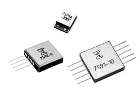
| Photo 4. MEMS capacitive and resistive accelerometers are placed in hybrid cans for circuit board mounting. The capacitive devices are lower left and lower right. The resistive device in the center is not to the same scale. The largest unit weighs 7 grams; the smallest, <1 gram. |
There is a continuous interest in decreasing the size of accelerometers. The smaller the mass of the accelerometer, the lower the probability that it will modify the response of the structure to which it is affixed. For example, ongoing R&D is assessing the dynamic mechanical response of aircraft fuselages to detect subsurface frame damage or very small fatigue cracks in the skin. Because these tests cannot tolerate any mass loading, scanning laser interferometers must be used.
For select test-and-evaluation applications, MEMS technology is allowing accelerometers to be built with a total mass of 1 gram or less. Circuit board mount configurations further reduce mass. The size of piezoelectric accelerometers is constrained by the manual dexterity of the assemblers involved in the manufacturing process, but improved assembly techniques are reducing the allowable dimensions (see Photo 5).
 | Photo 5. The 0.2 gram piezoelectric accelerometer with integral electronics shown here is 0.205 in. (5.21 mm) long and 0.100 in. (2.54 mm) thick. |
Increased High- and Low-Frequency Response
The verifiable limit for high-frequency accelerometer response is the upper frequency to which it can be calibrated. The current limitation at the National Institute of Standards and Technology is 15,000 Hz, but work is in progress that is expected to raise this limit to 20,000 Hz [3]. Even if accelerometers could be calibrated above 20,000 Hz, at high frequencies their mechanical impedance tends to modify the response of the structure on which they are mounted.
Pyroshock refers to short-duration, high-amplitude, high-frequency, transient structural responses in aerospace vehicles. Pyroshock on rocket or missile systems is attributable to explosive bolts and nuts, pin pullers, separation of spent rocket booster stages, linear cutting of the structure, and other actions that produce a near-instantaneous release of strain energy. To support structural analysis of typical military and aerospace systems, a 20,000 Hz frequency response is always more than adequate. Limitations in the modeling process preclude higher frequency requirements. However, the higher resonant frequencies possible with MEMS technology (see Photo 6) often increase the accelerometer's ability to survive a pyrotechnic event. In contrast, commercial piezoelectric accelerometers typically have a maximum resonant frequency 1/5 that currently achievable with MEMS technology.
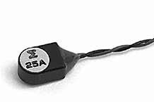
 | Photo 6. This 1.5 gram MEMS accelerometer is designed to withstand the severe shocks encountered in crash, blast, and impact environments. It features full-scale capabilities of 2000200,000 g, with a maximum resonant frequency of 1.2 MHz. |
Experimental modal analysis, or the ability to characterize structures empirically in terms of their damping, resonant frequencies, and vibratory mode shapes, has helped drive a demand for lower frequency response in accelerometers. The first vibratory mode of a transport aircraft such as the Boeing 737 or McDonnell-Douglas DC9 occurs at <1 Hz. This is the wing "butterfly" mode. The in-process space station and other large space structures have even lower structural frequencies. Experimental characterization of these structures is now possible using variable capacitance MEMS accel-erometers as well as piezoelectric accel-erometers. Piezoel-ectric types are not capable of frequency response to 0 Hz. Improved housing isolation from thermal and acoustic stimuli, however, results in designs with responses to <0.1 Hz (see Photo 7).
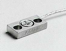
 | Photo 7. A piezoelectric accel-erometer design eliminates as many undesirable environmental effects as possible by preventing the coupling of acoustic, thermal transient, base strain, and various electrical effects into the ceramic elements. |
Increased and Decreased Amplitude Range
The demand for increased amplitude range in accelerometers over the past 510 years has not been great. Most of the effort has been directed toward increasing the sensors' pyroshock survivability. Pyroshock often excites an accelerometer's fundamental resonant frequency, causing the transduction element to mechanically amplify the event to the point of damaging the accelerometer. Increased amplitude ranges therefore help ensure survivability. The accelerometer in Photo 6 has a linear amplitude range of 200,000 g's.
As accelerometers achieve lower frequency response, the demands put on them to measure lower levels of acceleration increase. At lower frequencies, lower g levels are encountered. The previously described modal analysis of large space structures can easily require micro-g resolution at 0.1 Hz. Both MEMS and piezoelectric ceramic accelerometers have become readily available and have the requisite frequency response with sensitivities of 1000 mV/g and higher.
Increased Reliability
The limited number of measurements and the high cost of the system under test have historically generated demands on the part of military and aerospace customers for a high degree of reliability in accelerometer performance. As previously noted, when the accelerometer is permanently integrated into the system for control and monitoring functions, the reliability requirements are intensified.
A number of factors, two of which are mentioned here, have contributed to increased reliability. The elastic silicon flexural element containing diffused gauges, inherent in MEMS accelerometer design, has improved reliability over that offered by the earlier metallic flexures with bonded bulk semiconductor gauges. Moreover, silicon micromachining has enabled precise placement of overrange stops in both resistive and capacitive MEMS-type accelerometers, ensuring survivability in severe test applications. Probably the greatest increase in the reliability of MEMS and piezoelectric acceleration measuring systems has been a consequence of the trend of placing integral electronics in the accelerometer housing.
Integral Electronics
The first attempt at developing a piezoresistive accelerometer for the shock and vibration measurement community occurred in 1962 [4] and incorporated a patented butterfly bulk semiconductor gauge. During the 1970s, MEMS accelerometers began to become commonplace in the market. The past decade has increasingly seen MEMS accelerometers married to a separate chip containing electronic circuitry and packaged in a hermetically sealed housing. This has enabled a full-scale output signal level on the order of volts. In 1968 [4], a patent was filed to incorporate a 2-wire IC (FET) into a piezoelectric accelerometer. In time, all manufacturers of piezoelectric accelerometers endorsed this principle and more complex circuits were developed. Over the past 10 years, the demand for piezoelectric accelerometers with integral electronics has continued to increase. As is true of MEMS accelerometers with integral electronics, standardized low-impedance outputs providing signal levels of several volts are possible (see Photo 8).
 | Photo 8. An entire airborne acceleration measuring system contains power supply regulation, a charge amplifier, active filtering, and a biased output for telemetry compatibility. Weighing 28 grams, it replaces much bulkier flight systems that require several discrete modules. |
Options such as 28 ±4 VDC supply voltage, 05 V output, center-channel biasing of 2.5 V, and data filtering (see Figure 4) are all contained within the accelerometer housing. Not only do integral electronics offer the advantage of higher signal levels, but they also lessen the criticality of the accelerometer/cable connector or eliminate it altogether. In shock and vibration monitoring, the connector typically encounters the same environment as the accelerometer and has historically been a principal source of noise or cause of failure.
 | Figure 4. These frequency responses can be achieved with the filter options available in the accelerometer in Photo 8. The accelerometer contains all the electronics needed for compatibility with space telemetry applications. |
The focus of the 1990s, guided by IEEE (Institute of Electrical and Electronics Engineers) standards, is smart transducers. IEEE 1451.2 provides a definition of transducer electronic data sheets (TEDS) that are capable of interfacing with one or more transducers in individual smart transducer interface modules (STIMs). This standard will allow the transducer industry to design stand-alone STIMs for marketing to military or aerospace system integrators or end test users. The STIM could integrate the transducer(s), signal conditioning, digitizers, and address logic into a single package. What is the thermal sensitivity change, thermal zero correction, last calibration, and so forth of a given transducer? The TEDS could contain this information. The signal from a transducer could be corrected in near real-time. IEEE P1451.3 and P1451.4, when complete, are intended to move this technology further toward the marketplace. To envision the implications of smart transducers in the aerospace market, it is necessary only to imagine the structural dynamics qualification of a new airframe. Not only would the opportunity for misidentification of channels be lessened, but also much of the thousands of feet of cabling necessary for signal transmission could be eliminated.
Summary
A review of trends in accelerometer design intended to support the military and aerospace industry reveals a number of interesting developments in cost, size, frequency response, range, reliability, and integral electronics. Decreases in cost have resulted in increased use of accelerometers for control and monitoring. Size reductions continue to minimize mass loading of structures, while some increase in range is enhancing the pyroshock testing of aerospace components. Higher resonant frequencies are helping improve accelerometer survivability in pyroshock environments. Lower amplitude range and frequency response capabilities are enhancing the modal testing of large aerospace structures. MEMS sensor technology and the incorporation of electronics into the accelerometer housing are enhancing reliability. Smart accelerometers offer additional promise to the military and aerospace industry.
Challenges, however, remain. The truly high-volume application, analogous to the airbag accelerometer in automobiles, has not yet arrived. Hostile operating temperatures bar integral electronic accelerometers from many applications. Other extreme environments such as radiation, RFI, and EMFs can also create problems. Form factors and space allocations are additional constraints, particularly in military applications. It is nonetheless apparent that manufacturing processes will continue to enhance accelerometer design and surmount many of these challenges.
The Development and Application of High-Performance Accelerometer Sensor Technology for Military Applications will be addressed in a session at Sensors Expo Cleveland, 1416 September 1999.
References
1. Wayne Tustin and George Hibner. Oct. 1975. "Understanding and Measuring the Shock Response Spectrum," Spectral Dynamics Corp., SSA-3, San Diego, CA.
2. Chris Burroughs. Sept. 1998. "MicroNavigator team moving to take IMEMS technology from prototype to product," Sandia Lab News, 50:18, Albuquerque, NM.
3. B.F. Payne and G.B. Booth. 1995. "The NIST Super Shaker Project," Proc Eighteenth Transducer Workshop, Range Commanders Council, White Sands Missile Range, NM.
4. Patrick Walter. 1996. "History of the Development of the Accelerometer," 50 Years of Shock and Vibration History, The Shock and Vibration Information Analysis Center (SAVIAC), Arlington, VA:376-385.