Reliable and cost-effective 360-degree vision detection, enabled by various vision and non-vision sensors, is at the heart of development and commercialization of autonomous vehicles. With the strong push for ADAS and autonomous vehicles, the sensor market is projected to grow from $3 billion in 2015 to $35 billion by 20301.
One of the key autonomous functionality-enabling sensor systems is LIDAR, first used in the concept vehicles competing in the DARPA Grand Challenge for autonomous vehicles2. Lidar systems rely on time of flight measurement for emitted light from laser diodes to be detected by receivers after reflecting from objects in its path, and thus provide highly accurate information not only about object distance but also 3D data about an object’s width and height.
This article talks about some of the thermal challenges involved in designing LIDAR systems and how reliability is affected by the strategy chosen to integrate the system into a vehicle. We look at an example of a LIDAR product and how desired size, cost, performance goals can be met without negatively affecting sensor reliability.
Thermal Issues For Solid-State LIDARs
The latest solid-state sensors are essentially IC packages that must operate within specified temperature ranges for sustainable and reliable performance. Lidar sensors are unique in that the distance they can measure is affected by operating temperature3. For LIDAR systems that incorporate custom SoC (system on chip) ICs, the operating temperatures of internal components and external surfaces are influenced by the internal heat generation of the ICs, incident solar loading, surrounding temperature and air flow, and the cooling mechanisms.
The outer temperature of the enclosure also must meet safety requirements, and beyond that, the perception at which the temperature is “safe” to touch. If the surface seems too warm, this might lead to the conclusion that the system is malfunctioning or poorly designed.
Thermal simulation and analysis is used to ensure that designs meet these requirements. Thermal considerations in the design begins before any prototyping and ideally when the system is first architected. If thermal issues are considered before and in parallel with electrical and mechanical design, the overall design process can be shortened and result in a more robust product design. Thermal analysis early in the design process can quickly eliminate some options while indicating which designs will work better (Figure 1).

As the electrical and mechanical design evolves, the thermal aspects can be refined in parallel, clearly indicating which designs should be prototyped and tested. At this stage in the design process, electronic cooling simulation software, such as Mentor’s thermal simulation software, which is tightly connected with PCB design software (e.g., Mentor’s Xpedition) and mechanical CAD software (e.g., Siemens NX or SolidEdge), can be used by design engineers to create a detailed thermal model of the product4 and to simulate various designs and run optimization analyses.
In addition to thermal design exploration and optimization for the LIDAR system itself, design and reliability implications can be analyzed for a wide range of vehicle integration and use-case scenarios. For instance, solar radiation can be a significant factor for heat buildup or potential contribution of forced convective cooling for vehicle-mounted LIDAR when vehicle is being driven on a hot, sunny day. In addition, transient thermal behavior that considers differing vehicle-driving scenarios can allow engineers to determine the effects of temperature transients and the time it takes to reach a critical temperature condition. These simulation-driven analyses, from early prototyping stages, empowers LIDAR designers to account for various performance and life-limiting factors in their design and to conduct optimization analysis.
LIDAR System Example
Let’s look at the example of a solid-state LIDAR system that dissipates about 7 W of heat distributed over three stacked PCBs (Figure 1, Stage 3). The maximum IC power dissipation is 1.5 W for the two components located on the rear PCB and are referenced as the critical components. IC components can be critical in thermal design because of high power dissipation, high power density, or restrictive temperature limit. Critical ICs in a LIDAR thermal design could be any SoC or temperature sensitive sensor. Even at relatively low power dissipations, without the proper thermal design, the device performance can be limited with reduced reliability.
Effects of Enclosure and Location on Temperature
The heat generated from the LIDAR components is convected and radiated from the external enclosure surfaces. When transferring heat through convection from a solid surface to a fluid, total surface area in contact with the fluid plays a critical role. Design of this additional surface area in the device is highly dependent on the requirements for LIDAR integration into a vehicle.
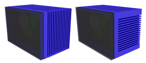
If the LIDAR is positioned so that it doesn’t benefit from the airflow caused by vehicle movement, then fins aligned vertically with gravity would typically be the recommended orientation (Figure 2). When the LIDAR system is exposed to forced air from the environment, the fins would be aligned with the predominant flow direction. In this example the air movement is left to right resulting in the fin alignment.

Whether the airflow is caused by buoyancy or external forces, the fins are best designed for the specific system. Thermal simulation software allows parameters such as fin count, thickness, and length to be optimized while directly modeling or simulating the effects on the overall system.
Depending on the air speed across the fins and the surrounding radiating surfaces, thermal radiation from the external surfaces where the LIDAR is mounted may also cause heat transfer. Because the heat transfer from the LIDAR is influenced directly by how and where it is integrated in a vehicle, the enclosure’s thermal design should include its mounted location and associated effects from that environment. When designing the fins, thermal performance is a primary concern but must be considered along with the weight, cost, and manufacturability of the enclosure.
Thermal Issues for Internal Electronics
Appropriate thermal management of the PCB and critical ICs on the board ensures good performance and reliability. Small form factors, desired for automotive use, even for low-power LIDAR, can pose significant challenges. Heat generated from the internal LIDAR components is convected, conducted, and radiated to the enclosure internal surfaces. Heat-transfer effectiveness for critical IC components can be improved through increasing heat-transfer surface area or by adding new conduction paths.
Placing a heatsink, or heat spreader, on a device can lower the component temperature. Figure 3 shows a heat spreader mounted on the two 1.5 W devices. Because of the size constraints of the LIDAR system, adding any surface area via a heatsink may not be desired.
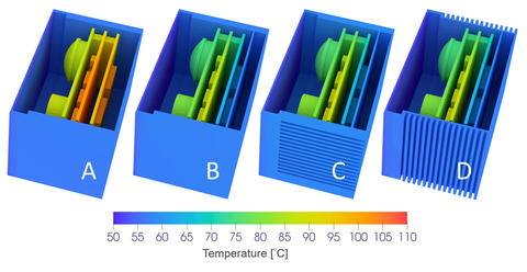
When a significant reduction in temperature is needed, adding a direct conduction path to the outer enclosure is recommended. Thermal conduction in solids such as aluminum is much more efficient that convection (and conduction) through air. A conduction path from IC components to the enclosure (Figure 3), results in component temperatures that operate at temperatures much closer to the enclosure temperature. The temperature reduction is influenced by IC heat dissipation and the thermal resistances between the IC and enclosure. While this design option has the benefit of reducing the IC temperature substantially, it can also lead to an elevated enclosure temperature.

In the example shown here, the relative benefits of the conduction and enclosure fin strategies were explored using the thermal simulation and analysis software. Simulations were done for a 35°C natural convection environment. The enclosure was assumed to have an emissivity of 0.9 for radiative heat transfer. Table 1 summarizes the results. The critical IC temperature refers to the 1.5 W component on the rear board with the higher operating temperature. The results show that including the conduction path reduced the critical IC temperature by 50%, from 104.8 to 66.5°C. This design change also resulted in an 18% enclosure temperature increase, from 57.4 to 61.5°C.

The addition of the conduction path reduced all of the temperatures with the LIDAR enclosure (Figure 4). The results also indicate that the fins, in their current form, provide no significant benefit.

Vehicle Integration
While many thermal design parameters may be considered with the LIDAR in a single scenario as we have examined here, sensor designers must account for the effects of vehicle integration early in the design stages. Vehicle integration introduces two important thermal considerations: 1) the solar radiation load depending on its mounted location, and 2) additional active cooling from forced convection while the vehicle is moving. Questions about the effects of airflow or the influence of neighboring systems can only be answered by a thermal-airflow model that includes variations on this data.
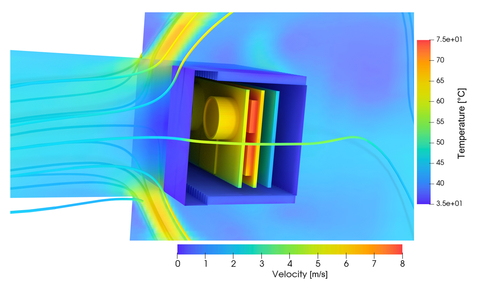
Let’s consider a scenario where a solid-state LIDAR (design C from Figure 4) is mounted in the front grill of a vehicle (Figure 5). Ambient temperature is 35°C, and for simplicity of analysis, the vehicle is driven at a constant speed of 10 m/s. We’ll add an incident solar load of 300 W/m2 with 50% absorption.
![Sensors Insights 2018-03-29 Fig5 Fig. 5: Grill-mounted LIDAR [design C] thermal simulation model.](https://qtxasset.com/styles/breakpoint_sm_default_480px_w/s3fs/sensorsmag/1522178930/FIG_5.jpg/FIG_5.jpg?itok=7ucNi8pa)
Figure 6 (for clarity, vehicle body isn’t included) shows that, near the fin area, about 3 m/s of airflow provides enough convective cooling. The enclosure surface temperatures are slightly above the ambient temperature of 35°C. The internal component temperatures range from 45°C to 75°C. Critical IC temperature dropped from 67°C in the natural convection study to 45°C when simulating in the 10 m/s environment. When not considering the environment in the simulation, there is a risk of over or under designing. Either way, the risk of uncertainty can be avoided if the thermal analysis considers external influences.

Solar radiation effect on the front-grill mounted LIDAR was minimal. However, for LIDAR that are mounted on the vehicle roof or other areas directly exposed to the sun, considerations for heating by solar radiation must be included. A wide range of analyses for LIDAR thermal behavior as a function of its mounting location can be easily performed using the framework we have described.
Thermal simulation of vehicle-integrated LIDAR systems also enables sensor engineers to develop appropriate temperature compensation algorithms for range and resolution estimates.
Digital Design and Simulation Can Speed Up AV Development
Testing autonomous vehicle functionality in extremely hot (for instance, Death Valley, Arizona) and cold (Minnesota winters) weather conditions is a critical part of vehicle verification and validation. Thermal simulation can be extremely useful for both sensor companies and vehicle manufacturers to ensure that LIDAR (and other sensors and autonomous functionality-enabling electronics) can function in extremely hot and cold weather conditions. With a workflow that integrates thermal simulation, electronics design software, and CAD, engineers can analyze any number of real-world traffic scenarios and avoid heavily relying on wind tunnel testing and/or full-vehicle testing. Accuracy of simulations is essential for design engineers to rely on the virtual design framework for making design decisions; and electronic cooling simulation software can be seamlessly calibrated with non-destructive thermal characterization to ensure accuracy5.
References
1. Yole Development (2015), “Sensors and Data management for Autonomous Vehicles,” https://www.i-micronews.com/report/product/sensors-and-data-management-for-autonomous-vehicles-report-2015.html?Itemid=0
2. “An Oral History of the DARPA Grand Challenge, the Grueling Robot Race that Launched the Self-Driving Car,” WIRED, August 3, 2017, https://www.wired.com/story/darpa-grand-challenge-2004-oral-history/
3. A. Alhashimi, D. Varagnolo, and T. Gustafsson (2015), “Joint Temperature-Lasing Mode Compensation for Time-of-Flight LIDAR Sensors,” Sensors, 15, 31205.
4. “A Step Change in Electronics Thermal Design: Incorporating EDA and MDA Design Flows,” http://go.mentor.com/4gt5d
5. F. Yake, W. Gang, X. Chen, W. V. Hon, X. Fu and V.V. Andras (2016), “Detailed Analysis of IC Packages Using Thermal Transient Testing and CFD Modelling for Communication Device Applications,” THERMINIC–22nd International Workshop on Thermal Investigations of ICs and Systems, Budapest.
About the authors
John Wilson is a Technical Marketing Engineer at Mentor Graphics, A Siemens Business. He received his BS and MS in Mechanical Engineering from the University of Colorado at Denver. Since joining the company in 1999, John has worked on or managed more than 100 thermal and airflow design projects.
Puneet Sinha is the Automotive Manager in the Mechanical Analysis Division of Mentor, A Siemens Business. Before joining Mentor, he worked at General Motors where he led global R&D teams to solve wide range of issues with fuel cells and battery electric vehicles and at Saft, a Li-ion battery manufacturer. Puneet received his PhD in Mechanical Engineering from Pennsylvania State University, has authored more than 20 journal articles, and has been awarded 7 patents on fuel cell and battery system design and operational strategies.