
Although our country is young by European, and especially by Asian standards, its infrastructures are getting old. These aging structures' rising costs are becoming an epidemic that directly affects public safety and has an adverse impact on the country's competitive advantage in the international marketplace. One area of particular concern is the nuclear power industry, whose aging cost has been estimated at an annual $17.3 billion [1]. The U.S. Nuclear Regulatory Commission considers the corrosion that has taken place in various facilities to be a public safety issue [2]. This article describes a nondestructive examination (NDE) process, and a new technology that could offer a cure for this "aging epidemic."
Two Events
The nuclear energy industry here and overseas has identified the sources of its aging problem as the result of both an aggressive operating environment and inadequate programs for predicting structure, system, and component remediation or replacement. One notable event was a leakage in France's Bugey Unit 3 nuclear power plant primary system in September 1991. The cause was a stress corrosion crack (SCC). In February 2002, serious erosion was discovered in the reactor head at the Davis-Besse Nuclear Power Station in Oak Harbor, Ohio (Figure 1). The affected area was identified as a bimetallic connection between a carbon steel vessel and a SS-clad surface welded to an iron-nickel-chromium pipe penetration. This material failure in an inherently corrosion resistant alloy surprised the industry. Similar material failures in U.S. nuclear facilities have led to a new approach to managing material reliability, but it has met with obstacles in its acceptance and implementation.
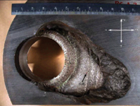 Figure 1. A football-sized eroded carbon steel section in the reactor vessel head exposed the nonpressure boundary cladding |
NDE Concept
A new nondestructive examination technique has been developed from earlier NDE work and from destructive evaluations of components and environments that have shown elevated permeability signatures in affected areas. The data thus acquired indicate a classic environmentally assisted stress-corrosion cracking model. This model simply suggests that material aging is due to property changes that are a function of grain boundary structure and strength deterioration [3].
These stages of deterioration can be detected by the correct NDE process and sensor technology. This new approach will provide the means to greatly enhance material reliability through effective remediation techniques, improved fabrication processes, and new corrosion-resistant materials.
Development Work
The development and application of the new NDE process presented challenges. The inspection area was characterized by limited access, complex geometry, interferences, and a high-radiation harsh environment. The sensor had to evaluate microscopic material changes (on the order of the Earth's magnetic field strength) to a depth of 20 mil. The severity of the environment also required the use of a remote examination system capable of navigating a congested area. This called for integration with a teleoperated robotic crawler with three degrees of freedom, a power supply, data collection and processing systems, and an umbilical cable to a remote control and analysis center. This remote scanner also needed axial, circumferential, radial, and tip-angle adjustment capabilities for an elliptical weld pool surface with a contour that goes from concave to convex (Figure 2).
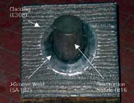 Figure 2. A mockup of a reactor vessel head penetration nozzle shows its J-groove weld |
The Sensor
Rather than using conventional inductive sensors, this eddy current probe uses frequency-independent magnetic sensors. The sensor package consists of a linear excitation coil, giant magnetoresistive (GMR) sensor array (Figure 3), and bias field conductors. The GMR sensors are bare-die versions of Wheatstone bridge GMR sensors commercially sold in mini small outline plastic packages. The use of bare die allows the sensors to be closer to the surface being tested. The dies are glued to the printed circuit board and die-bonded to the circuit board with gold wires.
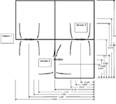 Figure 3. The sensor array at the end of the eddy current probe contained three GMR sensors |
The excitation coil has a diameter of 6.35 mm (0.25 in.) and operates at frequencies of 300–350 kHz. The GMR sensor has a magnetic field range of ±3.0 G and a sensing range of 254–2.54 μm (10–100 mil). The bias field conductor offsets the varying condition at 0–20 G and is controlled by an autobiasing circuitry. This circuitry was designed to prevent sensor saturation and to capture the magnetic field signatures >6 G. In this way, not only could the AC eddy current signal indicating mechanical flaws be measured, but also the DC magnetic state of the material indicating changed physical properties of the material could be detected.
The challenges for the sensor package lay in the selection and fabrication of the substrate material, in the connectors' configuration, and in finding a die that would be thin, flexible, and reliable. The sensor and circuit board were tested in mock-up at the Electric Power Research Institute NDE Center and Pacific Northwest National Laboratory facilities.
Remote Crawler and Scanner
The crawler incorporates drive wheels, uprighting motors, a lift, and a leveling platform. Four standard cameras are mounted on it for maneuvering through congested areas on the way to the inspection site. Encoder feedback and position sensors determine lift and verticality. The leveling platform maintains the scanner in its correct position. The scanner has three axes of movement: circumferential, radial, and axial, controlled by a motor informed by encoder feedback, and proximity sensors for positioning. The systems are powered by a 480 V, 3-phase, 60 Hz transformer that supplies 220 V to the crawler and 120 V to the excitation coil power supply, lock-in amplifier, and computer system.
Experimental Results
The eddy current test (ECT) demonstrated the capability of detecting and sizing SCC in the nozzle base material, J-groove weld, weld interface line, and cladding area (Figure 4). It was shown to detect and size flaws 2.29 mm (90 mil) long or 508 μm (20 mil) deep and extrapolates up to 2.29 mm (90 mil) deep with a tolerance of ±254 μm (10 mil).
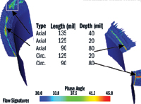 Figure 4. The system detected five induced stress corrosion cracks in a simulated penetration nozzle s J groove weld connection to a carbon steel plate with SS cladding |
The system inspected 48 penetration nozzles of the reactor vessel head, 12.82 m (422 ft.) of surface area, interrogating each one-millionth sq. in., and collecting and evaluating some nine million data points for flaw-like indicators that are generally not visible to the human eye. The evaluation was conducted in an environment of extreme radiation, boric acid deposits, surface plating, and fabrication imperfections that provided a multitude of material and surface imperfection signatures. The subsequent interpretation of these signatures required a new technique for data presentation (Figure 5).
 Figure 5. A contour, carpet mapping, and profile slice of the axial flaw area on the left side in Figure 4 provides clarity to the 25 MB of material characterization data |
Safer Generating Plants
The ability to assess the differing magnetic field intensities and field strengths, and simultaneously detect mechanical flaws by means of eddy current technology—in the hostile environment of a nuclear power generating facility—will go a long way toward identifying weakened structural components before they fail. This new nondestructive examination technology could thus enhance a plant's operational safety—and the safety of those who live and work in its vicinity.
Acknowledgement
The author wishes to thank Steve G. Price and Kenneth M. Williamson; and Robert W. Schneider and Dr. Carl H. Smith, both of NVE, for their support in the preparation of this article.
Kirby Woods, MSCE, PE, can be reached at InnoTech Engineering Solutions, Omaha, NB; 402-740-0281, [email protected].
References
1. "Cost of Corrosion in the Electric Power Industry," Electric Power Research Institute, No. 1004662, Oct. 2001.
2. "Order Establishing Interim Inspection Requirements for Reactor Pressure Vessel Heads at Pressurized Water Reactors," USNRC Order EA-03-009, Feb. 11, 2003.
3. "Transitioning from Paramagnetic to Ferromagnetic Surface Oxidation in the Nuclear Power Industry," National Association of Corrosion Engineers Material Performance, Nov. 2003.