Sensors are an important part of the overall system when it comes to automotive electronics. In today's vehicles, sensors monitor many electronic and electromechanical subsystems, gathering data and passing it onto the engine's electronic control unit (ECU) for processing. Sensors tell the vehicle's brain about speeds, temperatures, pressures, torque, oxygen levels, and more. All of it coalesces in the ECU, which uses the data to make near-instantaneous judgments about the vehicle's status and either initiates some kind of action in various subsystems or simply alerts the vehicle's operator to a condition that could cause functional problems or even safety hazards. Sensors can traffic in analog signals such as voltage or oxygen levels, digital signals, i.e., Hall-effect outputs for brushless dc motor speed and rotation direction, or serial data such as an embedded value in a CAN data packet.
There are a number of considerations when it comes to using oscilloscopes to test and debug sensors, and in this article, we will look at three key ones. For one, the ability to decode and debug serial-data streams is paramount. A second key consideration is the instrument's ability to acquire and display signals with small amplitude swings with high resolution. The third is the number of channels that an instrument offers.
Serial Data Considerations
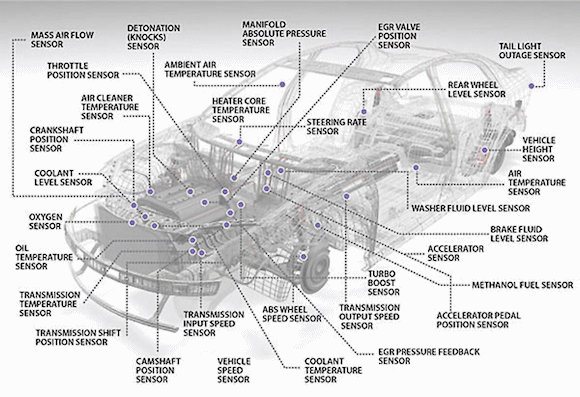
Vehicles are packed with sensors that feed into the on-board diagnostic (OBD) system and ECU (see fig. 1). Those communications take place using serial data links. The Ethernet, Controller Area Network (CAN), Local Interconnect Network (LIN), Media Oriented Systems Transport (MOST), FlexRay, and Peripheral Sensor Interface 5 (PSI5) protocols are among those found in such applications, as well as others based on the foundation of the Manchester line-encoding scheme. [Also see Decoding Manchester-Based Serial-Data Protocols For Sensor-to-Controller Applications]

Fig.1: Today's vehicles are packed with sensors for gathering data on speeds, temperatures, pressures, torque, oxygen levels, and more.
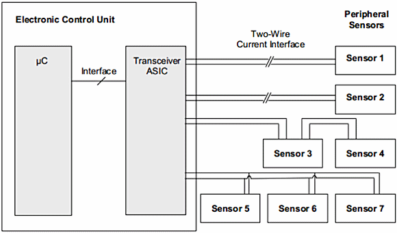
A system connecting myriad sensors to an ECU using the PSI5 protocol might resemble the block diagram shown in Figure 2. Sensors connect to the ECU with just two wires, using the same lines for power supply and data transmission.

Fig. 2: Shown is an example of a system setup for peripheral sensors connected to an ECU by means of the PSI5 bus protocol.
The transceiver ASIC provides a pre-regulated voltage to the sensors and reads in the transmitted sensor data. The example above shows a point-to-point connection for sensor 1 and 2 and two different bus configurations for sensors 3 and 4 and 5 to 7, respectively.
To properly design and debug communication between ECUs and sensors, be sure that your test instruments are properly equipped to decode the serial data stream. One example is Teledyne LeCroy's High Definition Oscilloscopes (HDOs), which can be configured to decode many different serial protocols. In general, the LIN protocol does a good job of serving low data-rate applications and CAN handles medium-speed requirements. The MOST protocol is tailor-made for high-speed tasks while FlexRay serves safety-critical applications such as steer- and brake-by-wire.
One interesting capability offered by the combination of modern oscilloscopes and associated software is the ability to create a virtual analog waveform from digital serial data. For example, Teledyne LeCroy's CANbus TDM (M=Measure/Graph) and ProtoBus MAG (MAG = measure, analysis, graph) packages provide a parameter that is essentially a digital-to-analog converter. This parameter extracts a serial data message and scales it to an analog value. If there are multiple analog values, as there would be in a serial-data sensor stream, the software presents the values as a waveform, in turn creating a virtual analog waveform from the digital serial data.
Small-Signal Handling
Most sensor applications involve relatively small voltage swings from high to low logic states. Rogue signals from undesired sources such as crosstalk can cause false switching errors. In such cases, an oscilloscope's vertical resolution can be a factor in determining and rectifying the causes.
Vertical resolution is a function of the instrument's analog-to-digital converter's (ADC's) resolution. ADCs have a resolution of 2n bits; early digital oscilloscopes were built using 6-bit ADCs, which yielded 26 bits of resolution, or 64 vertical quantization levels. Soon thereafter, next-generation oscilloscopes with 8-bit ADCs delivered 28 bits of resolution, which means 256 vertical quantization levels and a 4x improvement in vertical precision.
Until relatively recently, all oscilloscopes have employed 8-bit ADCs. Over the years, sampling rates have risen, which enables faster real-time signal acquisition. But the vertical resolution and precision have not fundamentally changed.
Today, the emergence of oscilloscopes with 12-bit ADCs in the data-acquisition chain gives automotive designers 4096 levels of vertical quantization with which to better debug sensor functionality. These 12-bit oscilloscopes, exemplified by Teledyne LeCroy's HDOs, present far greater signal detail as well as more accurate measurements. Because the instruments achieve true 12-bit resolution through hardware improvements and not through averaging or filtering, users may capture and display signals at the instrument's full sampling rate, which in the case of the HDOs is up to 2.5 Gsamples/s at bandwidths up to 1 GHz.
Channel Count
One aspect of oscilloscopes that most users take for granted is the number of channels that a given instrument provides. The most typical configuration seen on the market is four channels, which is the sweet spot for general design and debugging applications. However, when it comes to automotive systems (or, indeed, most embedded systems), more is better, and if the "more" includes digital channels, that is better still.
An example of a higher channel-count oscilloscope, Teledyne LeCroy's HDO8000, not only provides eight analog input channels but also 16 optional digital channels for clock rates up to 250 MHz. Applications such as automotive ECUs and mechatronics require not only the 16 digital channels for serial debug, but will greatly benefit from 12-bit HD4096 technology. Such applications often call for examination of 5V sensor signals with millivolt precision, as well as signals with wide dynamic range.
Often, one finds variable speed motor drives in automotive applications such as electric and electro-hydraulic power steering, electric water pumps, and so on. The combination of eight analog channels and 16 digital channels found in the HDO8000 is important when designing and/or debugging such applications. Note that the digital channels are particularly useful in working with sensors with streaming digital outputs, such as CANbus sensors or quadrature encoder interfaces.
For example, consider a typical PWM variable frequency drive (VFD). At the heart of the system is a VFD inverter; a common two-level, voltage-source inverter uses a "six-switch system" with the switches being three pairs of power semiconductors in the inverter's output. Each of the three pairs of switches controls the positive and negative voltage modulation activity of one of the motor's three phases.
For such applications, an absolute minimum of six analog input channels are necessary to view the three: phase VFD output to the motor itself (three voltage and three current). Having more than six channels would permit simultaneous viewing of signals from control lines, serial data, and/or sensors. The core applications, though are (a) looking at the three-phase output (three voltages/three currents/other signals) and (b) looking at the power semiconductor devices (VGS and VDS on as many devices as possible simultaneously to ensure proper switching operation).
Not only are there the three pairs of power transistors that make eight analog input channels so necessary, but there is also the matter of an MCU, interfaces to numerous sensors, and any number of serial protocols to debug. This is where the HDO8000's optional 16 digital channels come in.
Vehicular design and debug applications that involve sensors can be highly complex. In this article, we have covered just some of the considerations relative to test equipment for such applications.
About the Author
David Maliniak is Technical Marketing Communications Specialist at Teledyne LeCroy. He blogs, creates support documentation, and writes the occasional technical article. Before joining Teledyne LeCroy in 2012, David was Test and Measurement/EDA Technology Editor at Electronic Design Magazine.
Related Reading
Also see Decoding Manchester-Based Serial-Data Protocols For Sensor-to-Controller Applications.