

Accurate, repeatable temperature measurements are integral to many applications, so it's not surprising that temperature is the most commonly measured parameter. To ensure appropriate measurement precision in a cost-effective system, integrators must weigh various sensor types and the options for converting their outputs into actual temperature readings. Sensor technologies include thermocouples, resistive temperature detectors (RTDs), thermistors, and various semiconductor devices, all of which offer widely different measurement ranges, accuracy levels, price, and ease of use (Table 1). The best choice often depends largely on the application environment and temperature range required.
Table 1: Temperature sensing technologies
Thermocouples
Based on a simple operating principle, thermocouples are relatively easy to work with, but the wide range available makes it vital to pay attention to their metallurgy, the limitations of specific devices, and the treatment of measurement data. Thermocouples offer various advantages over other temperature sensors:
- They are typically inexpensive, although any required protective sheaths, cabling, and connectors can increase their overall cost.
- They are mechanically simple, durable, and reliable. Properties of typical metals used in thermocouples provide predictable output voltages, so users can adapt them to a variety of applications, including those in reactive or caustic environments.
- The physical construction of a basic thermocouple is simple—all it takes is twisting wires of the appropriate alloys together. However, commercial thermocouples are welded, crimped, or soldered; all methods produce similar results.
- Thermocouples offer choices spanning a wide overall temperature range, from about 100°C to beyond 2,500°C.
- Their accuracy is typically about ±1–2°C, which is more than sufficient for most applications.
Thermocouples' disadvantages, although relatively few, can significantly affect their usage and the hardware needed to read them. Thermocouple output is on the order of microvolts per degree Celsius, and thermocouples are sometimes located a significant distance from the system used to acquire them. To compensate, various signal conditioning techniques, including differential measurement mode, high gain, filtering, etc., are used to maximize the signal and minimize noise. The result is a relatively slow measurement rate, typically no more than a few hundred readings per second.
A thermocouple is a practical application of the "Seebeck Effect." Almost two centuries ago, physicist Thomas Seebeck discovered that the junction between two dissimilar metals generates a voltage that is a function of temperature. Historically, temperature measurement with thermocouples relied on a second thermocouple element to sense a known temperature as a reference. Once, the most common way of producing a reference temperature was to immerse the reference junction in an ice bath, which gave it the name cold junction. Today, however, many instruments, including switch cards for Keithley's Series 3700A and Series 2700 multimeter/switch systems, offer one or more reference junction functions.
Within any thermocouple's usable temperature range, there is a proportional relationship between thermocouple voltage and temperature. However, this relationship is by no means a linear one. In fact, most thermocouples are non-linear over their operating ranges. Obtaining temperature data requires converting the non-linear thermocouple voltage to temperature units through a process known as linearization.
When thermocouples are connected to the terminals of the measurement instrument, the connections form additional junctions that can generate unwanted thermoelectric voltages. Although a copper terminal pin plugged into a copper socket won't generate a thermoelectric EMF, a constantan pin or socket crimped to a copper wire results in a J-type thermocouple junction that will generate one. Extension wire and connector pins made from thermocouple metals are available to permit connection of like metals.
Thermocouples are often enclosed to protect them from the environment. A sheath (Figure 1) can protect the thermocouple element from contamination and physical damage from caustic materials, liquids, etc. Common sheath materials include iron, steel, stainless steel, iconel, ceramics, and porcelain.
Figure 1: Typical industrial thermocouple
Various metal alloys are used in thermocouple construction, with each offering characteristics advantageous for specific applications. Table 2 outlines the standardized letter codes assigned to these alloys. Each type of thermocouple wire can be identified by a color code for the individual conductors. Several color-coding systems are used around the world, but most indicate the negative thermocouple lead with red. Table 3 provides an overview of the color code system used in the United States.
Table 2: Thermocouple types
Table 3: Thermocouple color codes, United States
Base metal thermocouple types J, K, N, E, and T are economical, reliable, and reasonably accurate. They represent more than 90% of all thermocouples and are well suited for temperatures from 200° to 1700°C.
Because they are constructed of platinum and rhodium, Types R, S, and B are referred to as noble metal thermocouples. As a class, they are more accurate and stable than base metal types but also more expensive. They are used for applications up to 1,700°C, and as references for testing other types. To prevent contamination at high temperatures from metal vapors, they should be used inside a non-metallic sheath.
Resistive Temperature Detectors (RTDs)
RTDs are among the most stable and accurate temperature sensors available. They offer a narrower measurement range than thermocouples (approximately -200°C to +800°C), offering high accuracy and repeatability for food, laboratory, and pharmaceutical applications. Accuracy is often expressed as a percentage of resistance at a specified temperature.
The classic RTD configuration is a length of platinum wire wound on a glass or ceramic bobbin, which is then encapsulated in glass or other protective material (Figure 2). Another variety is constructed by depositing a conductive film on a non-conductive substrate, which is then encapsulated or coated to protect the film. RTD assemblies often include connectors, metallic sheaths, and handles and can resemble thermocouple probes.
Figure 2: Simple RTD
RTDs are based on the principle that the resistance of most metals increases with temperature. Most general-purpose RTDs are made of platinum wire. The resistances of platinum RTDs range from tens to thousands of ohms, but most have been standardized to a value of 100Ω at 0°C.
An RTD requires no reference junction, so it might seem a simple matter to connect a digital multimeter (DMM) to an RTD, measure its resistance, then convert to a corresponding temperature. However, the resistive properties of the RTD and associated wiring usually require sensitive instruments optimized for low resistances. For example, a 100Ω RTD having ? = 0.00385Ω/Ω/°C produces a resistance change of only 100Ω×0.00385Ω/ Ω/°C or 0.385Ω/°C. The wire leads connecting the RTD to the ohmmeter might have a value of several ohms. With a 100Ω RTD, 1Ω amounts to an equivalent temperature error of about 2.5°C.
Two options for converting resistance to temperature are available. One is simply to consult a look-up table and find the temperature corresponding to a specific resistance. This method is workable in software programs where an event will be triggered at a certain temperature (the corresponding resistance or voltage can be used as a trigger level) but isn't suitable for a real-time temperature readout. A second method uses an equation, most often a polynomial that uses a set of constants called the Callendar-Van Dusen coefficients.
The general equation for the relationship between RTD resistance and temperature is:
RTD = R0 [1+ At + Bt2 + C (t - 100)³]
Where: RTD is the resistance of the RTD at temperature t, R0 is the resistance of the RTD at 0°C, and A, B, and C are the Callendar-Van Dusen coefficients shown in Table 4. For temperatures higher than 0°C, the "C" coefficient is 0, and the equation becomes:
RTD = R0 [1+ At + Bt2]
Table 4: Callendar-Van Dusen coefficients for common RTD alphas
In an RTD, resistive ("joule") heating results from excitation current passing through the sensor (power = excitation current2 × RTD resistance). Although the amount of heat energy may be slight, it can affect measurement accuracy nonetheless. Self-heating is typically specified as the amount of power that will raise the RTD temperature by 1°C. Its typical value is about 1-mW/°C.
Inaccuracy caused by joule heating is aggravated by higher excitation currents and stagnant surrounding media of low specific heat. These effects can be minimized if the surrounding medium is in motion or is agitated to carry heat away from the RTD.
Thermistors
Although RTDs and thermistors (thermally sensitive resistors) are both resistive devices, they differ substantially in operation and usage. Thermistors (Figure 3) are passive semiconductor devices. The resistance of a negative temperature coefficient (NTC) thermistor decreases as its temperature increases, while the resistance of a positive temperature coefficient (PTC) thermistor increases as its temperature increases. NTC types are used more commonly than PTC thermistors for temperature measurement.

Figure 3: Thermistor
Although very small thermistors can respond quickly to slight temperature changes, they're prone to self-heating errors. They're also relatively fragile, requiring careful handling and mounting.
Thermistors offer a broader range of base resistance values than RTDs, with base resistance values from kilo-Ohms to mega-Ohms readily available. Compared to RTDs, the temperature coefficient of a typical thermistor is relatively large—on the order of several percent or more per degree Celsius. This high temperature coefficient results in a resistance change of up to several thousand ohms per degree Celsius. Therefore, the resistance of the wires connecting the instrumentation to the thermistor is insignificant, so techniques like high gain instrument inputs and three- or four-wire measurement configurations are unnecessary to ensure high accuracy. Thermistors are relatively low temperature devices, with a typical measurement range of –50°C to 150°C, although some can be used at temperatures up to 300°C. They're appropriate for applications that require sensitive measurements over a relatively restricted temperature range. Higher temperatures can decalibrate a thermistor permanently.
Thermistors produce a highly non-linear response, and are not as standardized as thermocouples and RTDs. Their manufacturers frequently supply resistance-temperature curves, tables, or constants for their specific products. Typical thermistor alphas (?) range from 2% to 8% per degree Celsius, and are generally larger at the lower end of the temperature range. Linearized thermistors also exist, although data acquisition systems and software make them unnecessary unless the readout hardware must be used with a linearized type.
For computerized applications, relatively accurate thermistor curves can be approximated with the Steinhart-Hart equation:
T = 1 / A + B x 1n (RT) + C [1n (RT)]³
T is the temperature in degrees Kelvin, which is equal to the Celsius temperature plus 273.15. RT is the resistance of the thermistor. The thermistor manufacturer should provide the constants A, B, and C for a given thermistor.
Instrumentation Options
A temperature measurement system's performance depends just as much on the measurement hardware used as it does on the sensors. If multiple sensors must be monitored, selecting appropriate switching hardware is also critical. Consider these questions during the selection process:
- What kinds of temperature transducers must the system be able to handle?
- How many temperature channels must the system be able to accommodate now and in the future?
- Does the application require measuring/monitoring temperatures in remote locations?
- Does the application require incorporating electrical measurements other than temperature into the system?
- What type of traceability is required for my measurements?
Although thermocouples, RTDs, and thermistors are compatible with many types of measurement instruments, digital multimeters (DMMs) are among the most common choices. Their inherently low noise design and traceable accuracy specifications make them well suited for temperature measurement applications. For applications that require monitoring temperature at multiple points, DMMs with integrated switching hardware are often the most compact and economical solution. For example, Keithley's Model 3706A System Switch/Multimeter (Figure 4) combines scalable, instrument-grade switching and multi-channel measurement in one enclosure.
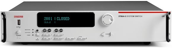
Figure 4: The Model 3706A System Switch/Multimeter supports up to 360 thermocouple channels in a single 2U chassis.
DMMs with integrated switching can greatly simplify the system configuration process and reduce system hardware costs. For example, the Model 3706A System Switch/Multimeter can accommodate up to 360 thermocouple channels in a single 2U chassis, and additional chassis can be integrated via the built-in TSP-Link™ interface. An LXI/Ethernet connection allows for simplified temperature monitoring in remote locations. Automatic cold junction compensation (CJC) is provided on the compatible Model 3720, 3721, and 3724 Multiplexer Cards and the instrument offers built-in support for three types of thermistors. An embedded graphing toolkit supports real-time data trending and analysis. In applications such as burn-in, which typically involve monitoring multiple temperature, voltage, and resistance measurements, these plotting capabilities simplify spotting trends over the course of a test.
Series 2700 mainframes (Figure 5) are similarly well suited for monitoring and logging temperature. Like the Model 3706A, they support three methods for cold-junction compensation (CJC): automatic (built-in), external, and simulated. A built-in channel monitor feature allows monitoring any specific input channel on the front panel display during a scan. This feature can also serve as an analog trigger to initiate a scan sequence based on some external factor, such as a temperature rising above a pre-set limit.
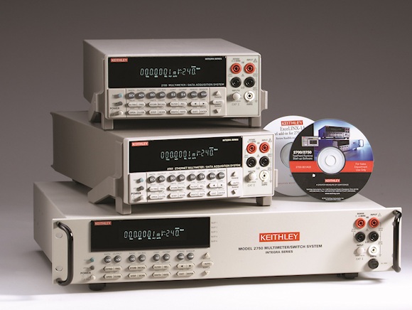
Figure 5: Series 2700 Multimeter/Data Acquisition/Switch systems are well suited for temperature measurement with support for thermocouples, RTDs, and thermistors.
The two-slot Model 2700 is designed for applications like temperature logging, precision measurement and control, and mixed signal data acquisition. A built-in 10/100BaseTX Ethernet interface makes the two-slot Model 2701 a good choice for distributed temperature measurement applications that demand stable, high precision measurements. With five module slots, the Model 2750 simplifies configuring solutions for measurement and control applications with hundreds of channels, such as power supply burn-in testing.
Conclusion
To learn more about temperature sensor and instrumentation options, download an application brief titled, Ensuring the Accuracy and Cost-Effectiveness of Temperature Measurement Systems.
About the Author
Jerry Janesch is a senior market development manager at Keithley Instruments, Inc., which is part of the Tektronix test and measurement portfolio. He earned a bachelor's degree in electrical engineering from Fenn College of Engineering and a master's of business administration from John Carroll University. He has been with Keithley since 2000.