
Last month I touched on some of the issues related to handling small signals. This month I will describe a technique called synchronous detection that can be used to recover very small signals buried in lots of noise.
Consider the case of an optical sensor used to measure a person's pulse rate. This sensor works by shining light from an LED into your skin and using a phototransistor to measure the amount of light reflected. The reflected light is an indicator of the amount of blood in your skin, which in turn varies with your heartbeat. In an ideal world, it would be very simple to measure heartbeat from the phototransistor's output current (Figure 1). In our very non-ideal world, however, several effects will conspire against easily retrieving the signal from the phototransistor. Some of these include ambient light, the phototransistor's leakage current, and noise.
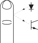 Figure 1. Pulse rate can be determined by shining an LED light into your skin and measuring the reflected light, which in turn indicates heartbeat |
One way to get around a lot of these problems is to modulate the signal you are trying to detect. In this example, this might mean flashing the LED at 10 kHz or so. So instead of trying to detect a very small low-frequency signal (Figure 2A), we are now trying to detect a very small high-frequency signal, modulated by a heartbeat (Figure 2B). What are the advantages?
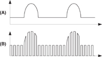 Figure 2. Signal modulation lets you go from trying to detect a very small low-frequency signal (A) to a very small high-frequency signal (B) |
Well, there are several. The first is that it becomes very easy to ignore any signal resulting from ambient light picked up by the phototransistor. It can be difficult to discriminate a 1 Hz heartbeat from continuous room lighting levels because 1 Hz optical signals can also be generated by people moving around in a room. It is very easy to discriminate a 10 kHz signal from natural lighting, though, as there aren't very many objects in nature that generate 10 kHz optical signals.
Another advantage is that it becomes possible to ignore the phototransistor's leakage current, as well as DC offset voltages at the front-end amplifier. These also are DC artifacts.
A subtle advantage that comes from using a high-frequency modulated signal is that many precision electronic systems have their worst noise performance at low frequencies, due to what is known as 1/f noise. By moving the frequency of interest up into the kilohertz range, you can often get better noise performance out of your amplifier.
The advantages of using modulated signals to transmit information in the presence of noise and interference should be familiar to anyone who knows how a radio works. In a sensor system like the one described above, however, we have a big advantage over a radio receiver: In addition to knowing the frequency of the signal we are looking for, we also know the phase. This makes it possible to realize very simple, yet extremely selective signal recovery circuits.
So what does a signal processing system for this sensor look like? Figure 2 shows a high-level clock diagram, along with some idealized signals. An oscillator both modulates the LED and provides a reference signal for the detector circuit (A). The optical signal goes into the sensed object; the return signal is picked up by the phototransistor and subsequently amplified to a level where it can be conveniently handled. It may also be desirable to remove any DC component of the signal at this point. You can use a simple DC-blocking filter (B).
Now that we have an amplified version of the raw signal, we can recover it with a synchronous detector. This device is basically a demodulator, or a multiplier circuit. In examples such as the one described here, where an ON-OFF modulation is used, the synchronous detector can be as simple as an amplifier with a selectable gain of +1 or –1 (Figure 3). When the modulating signal is high, the gain of +1 is selected; when it is low, you want a gain of –1. This results in the raw demodulated signal (C). This signal is then low-pass filtered to yield a final measurement signal (D).
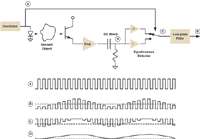 Figure 3. A synchronous detector with a selectable gain of +1 or –1 allows you to dig a modulated signal out of the "mud" |
When you look at the idealized waveforms in Figure 3, you might not see what the big advantages of synchronous detection really are, but what's going on is pretty clear. The technique really shines in situations where the signal of interest is buried in lots of noise. With proper use of the technique it is often possible to cleanly recover a modulated sensor signal that is so far "down in the mud" that you can't see any indication of it on an oscilloscope.
Ed Ramsden, BSEE, a member of the Sensors Editorial Advisory Board, designs sensors for the heavy-truck industry in Portland, OR.