
Strain gauges are sensing devices that change resistance at their output terminals when stretched or compressed. They are typically bonded to the surface of a solid material to measure its minute dimensional changes when put into compression or tension. Strain gauges and their underlying principles are often used in devices for measuring acceleration, pressure, tension, and force. Strain is a dimensionless unit, defined as a change in length per unit length. For example, if a 1-m-long bar stretches to 1.000002 m, the strain is defined as 2 microstrain (µε). Strain gauges have a characteristic gauge factor, defined as the fractional change in resistance divided by the strain. For example, 2 µε applied to a gauge with gauge factor of 2 produces a fractional resistance change of (2 × 2) 10-6 = 4 3 10-6, or 4 µΩ. Common gauge resistance values typically range from 120 to 350 Ω, but some devices can be as low as 30 or as high as 3 kΩ.
Strain Gauge Configurations
To obtain accurate strain data, extremely small resistance changes must be measured. A Wheatstone bridge circuit is widely used to convert the gauge's microstrain into a voltage change that can be fed to the input of the A/D converter (ADC), as shown in Figure 1. When all four resistors in the bridge are absolutely equal, the bridge is perfectly balanced and Vout = 0. But when any one or more of the resistors change value by only a fractional amount, the bridge produces a significant, measurable voltage. When used with an instrument, a strain gauge replaces one or more of the resistors in the bridge, and as the strain gauge undergoes dimensional changes (because it is bonded to a test specimen), it unbalances the bridge and produces an output voltage proportional to the strain.
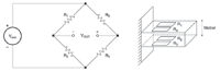 Figure 1. The full-bridge circuit provides the largest output with the fewest errors. All four arms of the bridge are active; two are in tension and the two on the opposite side are in compression. |
Full-Bridge Circuits. Although half-bridge and quarter-bridge circuits are often used, the full bridge is optimal for strain gauges. This circuit has the highest sensitivity, the fewest error components, and the highest output that reduces the effects of noise on the measurements.
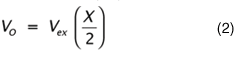
A full-bridge circuit contains four strain gauges mounted on a test member: two on the surface under tension and the other two on the opposite surface under compression, as shown in Figure 1. As the member deflects, the two gauges in tension increase in resistance while the other two decrease, unbalancing the bridge and producing an output proportional to the displacement. The bridge output voltage is given by:
where:
V O = bridge output voltage, V
Vex = excitation voltage applied to the bridge, V
X = relative change in resistance, ΔR/R
The bridge nulls out potential error factors such as temperature changes because all four strain gauges have the same temperature coefficient and are located close to one another on the specimen. The resistance of the lead wire does not affect measurement accuracy so long as the input amplifier has high input impedance. For example, an amplifier with a 100 MΩ input impedance produces negligible current flow through the measurement leads, minimizing voltage drops due to lead resistance.
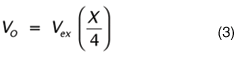
Half-Bridge Circuits. When physical conditions do not allow mounting a full-bridge gauge, a half bridge might fit. Typically, two strain gauges are mounted on a test member, and two discrete resistors complete the bridge (see Figure 2). The output voltage is:
 |
where:
VO = bridge output voltage, V
Vex = excitation voltage applied to the bridge, V
X = relative change in resistance, ΔR/R
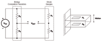 Figure 2. In a half-bridge circuit, only two arms are active. Two strain gauges are on the specimen, and the two fixed resistors completing the bridge are not. |
For a large ΔR, half-bridge and quarter-bridge circuits can introduce an additional nonlinearity error. Also, the readings are not accurate when the temperature coefficients between bridge completion resistors and strain gauges are different and the resistances do not change proportionally with temperature. Furthermore, bridge completion resistors are not usually located near the strain gauges, so temperature differences contribute additional errors. In systems with long lead wires, the bridge completion resistors should be attached close to the gauges, but this might not always be practical due to test fixture limitations or other physical conditions.
Quarter-Bridge Circuits. A quarter-bridge circuit uses one strain gauge and three bridge completion resistors. The output voltage is:
 |
where:
VO = bridge output voltage, V
Vex = excitation voltage applied to the bridge, V
X = relative change in resistance, ΔR/R
This arrangement has the smallest output, so noise is a potential problem. Furthermore, all the error sources and limitations in the half-bridge apply to the quarter bridge circuit (see Figure 3).
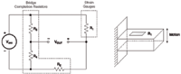 Figure 3. A quarter-bridge circuit uses only one active arm and is the least sensitive of the three types. It is also the most prone to noise and errors. |
Excitation Source
Accurate measurements depend on a stable, regulated, and low-noise excitation source. A regulated source is necessary because the output voltage of a strain gauge is also proportional to the excitation voltage, so fluctuations in the excitation voltage produce inaccurate output voltages. An ideal data acquisition system provides an excitation source for each channel, independently adjustable from 0.5 to 10.5 V with a current limit of 100 mA. An excitation voltage, V, used with a strain gauge of resistance, R, requires a current of I = V/R. The resistance of a Wheatstone bridge measured between any two symmetrical terminals equals the value of one of the resistance arms. For example, four 350 Ω arms make a 350 Ω bridge. The load current equals the excitation voltage divided by the bridge resistance; in this case, 10 V/350 = 0.029 A = 29 mA.
Heating
Resistive heating in strain gauges also should be considered because the gauges respond to temperature as well as stress. In most standard circuits, the heat that each gauge dissipates is <100 mW, so it's usually not a problem. This is especially true when the strain gauge is bonded to a material that conducts heat quickly, such as metal.
However, because materials such as wood, plastic, or glass do not conduct heat away as rapidly, it is a good idea to use the lowest excitation voltage possible without introducing noise problems. Heat can become a problem when the strain gauges are uncommonly small, or numerous gauges occupy a limited space.
Consider a Kelvin connection for applying the excitation voltage. Because the excitation leads carry a small current, they drop a correspondingly small voltage, V = I/RL, which reduces the voltage reaching the bridge terminals. As illustrated in Figure 4 Kelvin connections eliminate this drop with a pair of leads added at the excitation terminals to measure and regulate the bridge voltage.
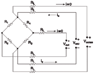 Figure 4. The Kelvin bridge circuit uses one pair of wires to provide the excitation voltage directly at the bridge, and another to sense the excitation voltage. A third pair of wires measures the bridge output voltage. This arrangement removes the voltage-drop error in the excitation wires from the measured strain signal. |
For instance, when Ie = 50 mA, RL = 5 V, and the combined voltage drop in the two leads is 500 mV, no voltage drops in the sense wires.
A commercial unit uses a Kelvin connection to measure and regulate the voltage at the bridge. It supplies the voltage to the strain gauge with one pair of leads and measures it with another pair (see Figure 5). The six wires are used in pairs for Sense, Excite, and Measure. The Sense lead is a feedback loop that ensures the Excite voltage is constantly held within specifications.
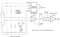 Figure 5. A commercial strain gauge module provides adjustable excitation, gain, and offset for each channel, so it can make use of the instruments entire dynamic range. |
Signal Conditioning
Most strain gauge–based transducers and load cells are assigned units of measure for weight, force, tension, pressure, torque, and deflection with a full-scale value measured in mV/V of excitation. For example, a load cell with a 10 V excitation supply and a 2 mV/V gain factor generates an output of 20 mV at full load, whether the load cell was designed to handle 10, 100, or 1000 lb.
The difference lies in the resolution of the system, i.e., the small 10 lb. load cell produces 0.5 lb./mV, and the large 1000 lb. unit produces 50 lb./mV.
Conductors carrying such low-level signals are susceptible to noise interference and should be shielded. Low-pass filters, differential voltage measurements, and signal averaging are also effective for suppressing noise interference. Furthermore, instrumentation amplifiers usually condition the extremely low strain gauge signals before feeding them to ADCs. For example, a 10 V F.S. input provides 156 µV of resolution for a 16-bit ADC. The amplifier gain should be adjusted to provide the full-scale output of the strain gauge or load cell over the converter's entire range. Force and pressure transducers typically generate an offset output signal when no external force is applied. Instrumentation amplifiers usually contain a control to adjust this offset to zero and let the load cell cover the full range of the ADC. Most instruments also provide adjustable excitation, and gain.
Common Mode Rejection Ratio
A high common mode rejection ratio (CMRR), a measure of how well the amplifier rejects common mode voltages, is essential for strain gauge amplifiers. A strain gauge signal in a Wheatstone bridge is superimposed on a common mode voltage equal to half the excitation voltage. For example, consider a 10 V excitation supply (Vmax = 5 V) for a strain gauge with 2 mV/V (Vs = 20 mV) at full scale and an amplifier with a CMRR of 90 dB (see Figure 6). The amplifier can introduce 0.158 mV of error, corresponding to ~0.80% F.S.,
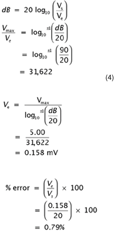 |
which may not be acceptable:
where:
Ve = error voltage, 0.158 mV
Vs = signal voltage, 20 mV
Vmax = maximum voltage, 5 V
CMRR = 90 dB
By comparison, a CMRR of 115 dB introduces only 9 µV of error, which corresponds to only 0.04% of full scale.
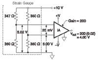 Figure 6. The strain gauge signal in a Wheatstone bridge is usually superimposed on a common mode voltage equal to half the excitation voltage. Consequently, a high common mode rejection ratio is necessary to reject the common mode voltage and amplify the strain gauge signal. |
Strain gauge signal-conditioning modules usually provide a regulated excitation source with optional Kelvin excitation.
Onboard bridge completion resistors may be connected for quarter- and half-bridge strain gauges. Instrumentation amplifiers provide input and scaling gain adjustments, and an offset adjustment nulls large quiescent loads. This allows input signals to use the full range of the data acquisition system, and the measurements cover the full resolution of the ADC.
Some strain gauge signal conditioners provide fixed gain, offset, and excitation settings, but fixed settings do not take advantage of the ADC's maximum dynamic range. Rather, they decrease the actual available resolution of the measurement. For example, many generic strain gauge signal conditioner modules can be set to a fixed 3 mV/V rating. At 10 V, the excitation, offset, and gain trimming are all fixed and no adjustments can be made.
An excitation adjustment lets users set the excitation voltage to the maximum allowed by the manufacturer, which maximizes the bridge's output. Also, the offset adjustment lets users zero the output offset produced by either a small bridge imbalance or a quiescent deformation of the mechanical member. And the gain adjustment lets users set a gain that provides a full-scale output under maximum load, which optimizes the dynamic range of the ADC.
Calibration
The signal-conditioning module also typically provides a shunt calibration feature (see Figure 7) that lets users switch their own shunt resistors into either one of the two lower legs of the bridge under software control.
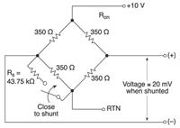 Figure 7. A bridge may be calibrated with a shunt resistor that is switched by means of a software command into either of the two lower legs. |
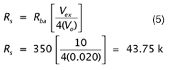
For example, a shunt resistor can be calculated to simulate a full load, which is a convenient way to simulate an imbalance without having to apply a physical load. For any balanced bridge, a specific resistor can be connected in parallel with one of the four bridge elements to obtain a predictable imbalance and output voltage. For example, a 350 V, 2 mV/V strain gauge delivers full output when one leg drops by 0.8% to 347.2 V. A 43.75 kΩ resistor shunted across one or the other lower bridge elements swings the output to full positive or full negative. An equation for calculating the shunt calibration resistor value is:
 |
where:
Rs = shunt resistor, Ω Ω
Rba = bridge arm resistor, Ω Ω
Rs >> Rba
Vex = excitation voltage, V
VO = bridge output voltage, V
Many products include calibration software with a Windows-based program that provides several calibration methods, online instruction, and a diagnostic screen for testing the calibrated system.
Applications of the Technology
Transducers and Load Cells. Strain gauges are commercially available in prefabricated modules such as load cells that measure force, tension, compression, and torque. Load cells typically use a full-bridge configuration and contain four leads for bridge excitation and measurement. The manufacturers provide calibration and accuracy information.
Strained-Diaphragm Pressure Gauges.
These devices consist of two or four strain gauges mounted on a thin diaphragm. The gauges are wired in a Wheatstone bridge circuit, including bridge completion resistors when needed, so the pressure gauge is electrically equivalent to a load cell. The output voltage is specified in mV/V of excitation for a full-scale pressure differential across the diaphragm.
When one side of the diaphragm (the reference pressure side) is open to the ambient atmosphere, the gauge compares the inlet pressure to the ambient pressure, ~14.7 psi at sea level. When the gauge measures ambient pressure, the reference chamber must be sealed with either a vacuum reference (near zero psi) or the sea level reference.
Temperature variations can affect the accuracy of these gauges. A pressure gauge with a sealed non-zero reference pressure exhibits temperature variations consistent with the ideal gas law. For example, a 5°C change in ambient temperature near normal room temperature (25°C) produces an error of 1.7% in the pressure measurement. Temperature variations can also affect the performance of the strain gauges themselves. Transducers must contain temperature compensation circuits to maintain accurate pressure measurements in environments with widely varying temperatures.
All strained-diaphragm pressure gauges require a regulated excitation source. Some gauges contain internal regulators that allow users to connect an unregulated voltage from a power supply. Some also have internal signal conditioning that amplifies the millivolt signal output of the Wheatstone bridge to a full-scale voltage from 5 to 10 V.
Gauges of this type have low-impedance outputs. In contrast, other pressure gauges have no internal signal conditioning; their output impedance equals the Wheatstone bridge resistance (several kilohms for semiconductor types), and their full-scale output is in millivolts.
This article was adapted from the Signal Conditioning & PC-Based Data Acquisition Handbook, 3rd Ed., 2004, ed. John R. Gyorki, $29.95, available from IOtech, Inc.
John R. Gyorki is Senior Project Engineer, IOtech, Inc., Cleveland, OH; 440-703-2307, [email protected], www.iotech.com.