
Rising fuel prices, coupled with tightening regulations on vehicle efficiency and emissions, are creating a global demand for higher levels of precision in torque measurement on test stands for engines and transmissions. On one hand, torque values must be certifiable to meet regulations and manufacturers' specs. On the other, they must be precise enough to pick up efficiency differences of 0.1% or less in the test object. Such tight system accuracy requirements mean that the torque flanges themselves must be accurate to within 0.05%.
Item: Pressure to streamline manufacturing throughout the automotive and turbine industries is creating a demand for more compact, more versatile test stands that also deliver high accuracy. This just about rules out older barrel-type torque sensors because of their size, mass, and dynamic range limitations.
Fortunately, newer digital torque flanges are able to meet these demands. We'll take a look at one example (Figure 1) later on. But let's first consider some general principles of high-precision torque measurement.
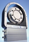 Figure 1. The new T12 digital torque flange |
Some Basic Principles
Don't Overspecify. Define reasonable requirements for system accuracy. This is important strategically as well as technically. At the design stage for an engine, turbine, or transmission, more accurate torque data can give you a distinct advantage in a very competitive world market. The more accurate the data, the closer to the limits you can safely design. Torque differences due to different lubricants in an engine, though small, are nonetheless important in the global auto business. And it takes a sensitive torque test to reveal them.
For these reasons, developmental torque testing of engines and drivetrains may increasingly need 0.3% system accuracies, attainable only with properly installed advanced digital torque flanges. Calibration may require 0.008% total system accuracy. By contrast, most production cold-engine testing in automotive plants needs only 1%–3% system accuracy.
Overspecifying accuracy or resolution requirements will add unnecessary cost, slow down the test, consume memory, and actually make it harder to find what you are looking for. It's the same principle as sending images over email. A 1000 dpi image takes twice as long to print or send as a 500 dpi image, twice the file space to store, and twice the time to retrieve or scan.
Recently, for instance, a turbine manufacturer inquired about components for a production test stand, insisting on total system accuracy within 0.1% over the entire dynamic range. This simply isn't possible because of the physics of the system. Errors arise from too many sources: the coupling shaft, the test-stand transmission, temperature variations, structural deflection, and sensor mounting errors, to name just a few. After an hour's discussion, he still wasn't satisfied and said he'd call other providers. A week later, he called us back with an order for what we had recommended in the first place. In the process, he lost a week from his schedule and a lot of man hours.
Six Tips You'll Find Handy
When you do need truly high precision torque measurement, here are some guidelines to keep in mind.
- 1. Look for the lightest digital torque sensor that can meet accuracy specs. All things being equal, a light torque flange will introduce less system error than a heavier one. And a modern digital torque flange is intrinsically more consistently precise than a mechanical or analog torque sensor.
- 2. When you need an amplifier, get it and the torque flange from the same supplier. Doing so will ensure compatibility of characteristics that might not be listed in the specifications of either. If you must mix sensor and amplifier brands, at least be sure that their frequencies and phases match. (Note: transducer-type torque flanges such as the new T12 do not need an amplifier.)
- 3. Be careful about mounting the torque flange—especially alignment, bolt tightening, and orientation between stator and rotor. Be sure the mating surfaces are smooth and clean. The very act of mounting the torque flange introduces strains that can affect base readings. Even the wrong bolt materials can throw off the results. Always follow instructions in the manual to the letter. A surprising share of support calls we receive from integrators or users trace back to improper mounting.
- 4. Improperly mounting a torque flange will inevitably introduce a side load, which pre-stresses the transducer. Compensate for it when zeroing the system. Use a flexible coupling that is torsionally stiff but radially flexible.
- 5. Be sure all components are properly grounded. Include all cables and plugs in the grounded Faraday cage, not just the sensors, amplifiers, and displays.
- 6. Even digital torque flanges need periodic calibration. Be sure to calibrate them against a true reference transducer at least once every two years. Amplifiers in a torque testing system need calibration at least annually.
The T12 Digital Torque Flange
The recently introduced T12 digital flange offers full-scale linearity of 0.03% (optional to 0.01%) and 19-bit resolution. Models currently available cover nominal torques from 500 N-m to 3 kN-m and speeds from 12,000 to 16,000 rpm. System safety and control features include built-in self-diagnostics and storage of calibration data, extreme values, and temperature. A parameterized CAN interface facilitates setup. Outputs are selectable among CANopen, Profibus, RS-422, 10 V analog, or 60 or 10 kHz. The T12 is a completely wireless, self-contained transducer that requires no external amplifier, slip rings, or mechanical connections. This design both simplifies setup and minimizes maintenance.
Target applications include performance testing of engines and power train components that require a wide dynamic range, and test stands with limited space or weight/mass moment or inertia allowances. This means development testing more than production-line QA, which usually doesn't demand so much accuracy and versatility. The T12's accuracy and resolution allow a single unit to handle a wide dynamic range without having to switch signal ranges or change torque flanges midway through a test. This saves time and reduces sensor inventory requirements.
Some Specific Details
Electronics in the rotor (Figure 2) measure torque and temperature, generate the shunt signal, and store the identification, calibration, and extreme-value data. Separate circuit boards, also in the rotor, handle the analog and digital sections.
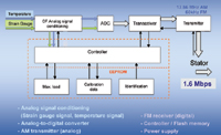 Figure 2. Functional diagram of the T12 rotor. The large arrows represent data; the thin black arrows are commands. |
Circuitry in the stator (Figure 3) handles rotational speed measurement, temperature and speed compensation, filtering, and scaling of analog inputs. The power module, high-frequency section, controller module, and extension modules are on separate boards.
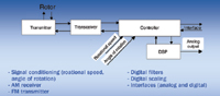 Figure 3. Functional diagram of the T12 stator |
If You Need It, It's There
Not every torque test needs fifth-decimal-place precision, and it can be a mistake to specify more precision than you really need. But when you do need it, which is increasingly the case in engine development worldwide, the technology exists to achieve it. And more precise torque testing in the development process can create opportunities for competitive advantage for any power train component.
Bob Davis, BSME, BS Materials Science, can be reached at HBM Inc., Marlboro, MA; 508-624-4500, [email protected], www.hbm.com.