
Before the digital technology explosion of the 1970s and 1980s, carrier frequency (AC) excitation of strain gauge–type devices (e.g., load cells and pressure sensors) was quite common, especially for applications characterized by varying temperatures and long measurement lead lengths. As digital technology progressed, it became possible to place the strain gauge signal conditioning close to the actual sensor. This allowed standard DC excitation to become equally accurate and much less expensive.
Over time, and to no seasoned engineer's surprise, measurement precision, stability, and speed requirements have increased. AC excitation never disappeared but was relegated to tough specialty applications that demanded high-performance capabilities and justified the steeper cost.
Today, that premium has been reduced to the point where AC technology is attractive for cost-sensitive industrial measurement applications.
Modern digital technology has brought the additional benefits of high resolution, high sampling rates, flexible signal processing, and numerous data transfer options. The resulting new products can be used in applications in which they are cost-effective and can be installed without changing existing transducers or control systems, and where standard DC technologies just can't deliver the results.
An Overview of Strain Gauges
If a strip of conductive metal is stretched, it will become thinner and longer. These changes result in an increase of electrical resistance from one end to the other. Conversely, if a strip of conductive metal is compressed, it will thicken, shorten, and decrease in resistance. If these stresses are kept within the elastic limit of the conductive metal strip (i.e., no permanent deformation occurs), the strip can be used as a measuring element for physical force, and the amount of applied force can be determined by measuring the change in resistance.
This type of device is called a strain gauge and is typically used to measure stresses generated in material. Most modern strain gauges are made by plating a thin layer of metal onto a polymer substrate. The device is bonded to the surface of the item where strain or deflection is to be measured (Figure 1). One common application is aircraft component testing, where strain gauge strips are glued to structural members or other critical components of an airframe to measure stress.
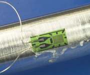 Figure 1. An example of a strain gauge bonded to a sample undergoing tensile-strength testing |
But applications using strain gauges do not have to be exotic. For example, electronic scales typically use a strain gauge to measure the weight of objects on the scale. Also, many pressure sensors use an engineered diaphragm with a strain gauge to electrically determine the applied pressure. In addition, one of the most common ways engineers and technicians encounter strain gauges is by using load cells. A load cell is just a strain gauge applied to a metal bar with known characteristics inside a pre-engineered package to measure a specific range of applied force.
Although the resistance of the strain gauge varies with the force applied, it does not vary much (typically only a fraction of 1% over the full force-rated range of the gauge). Therefore, the measurement instrument must be precise. To measure these small changes, a resistor-bridge (sometimes called a Wheatstone bridge) measurement technique is used. In many applications, a full-bridge configuration is used because it provides the most robust measurement, but it requires four strain gauges (Figure 2). In other applications, half- and quarter-bridge circuits can be used. In these applications, fewer strain gauges are deployed, and the others are replaced by appropriate resistors in the measurement instrument. This is called bridge completion.
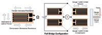 Figure 2. Typical strain gauge |
DC excitation (the battery in Figure 2) can be easily replaced with an AC signal source. This is possible because the measurement circuit is simply a bridge of resistors, and it operates just as well with AC or DC voltage.
Measurement Instruments
Today, most strain gauges and load cells use a simple DC voltage to excite the resistive bridge elements (Figure 3). This time-proven method is adequate for many applications, but it requires the measurement instrument to process a wide bandwidth of electrical signals, which may include noise.
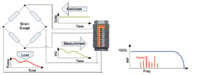 Figure 3. The DC signal will be modulated by the mechanical quantity (force, strain, and torque). The transmitted frequency range is between 0 and 10,000 Hz (or more). All frequencies have to be transmitted for dynamic measurements, including noise |
Taking advantage of the fact that the actual bridge elements are simply resistors, you can obtain higher performance when the elements are excited by an AC signal (Figure 4). This technique works in much the same way as amplitude-modulated (AM) radio and allows the measurement instrument (the receiver) to "tune out" all other frequencies except the one of interest (the frequency of the AC excitation signal). The AC excitation is a known frequency (fc), so when the resulting force-modulated signal is decoded, only a small bandwidth of electrical signals around fc must be considered. All other signals in surrounding frequencies are ignored, including noise.
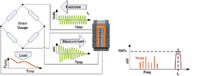 Figure 4. The AC signal (carrier frequency fc) is modulated by the mechanical quantity (force, strain, torque). The transmitted frequency range is only a small band around the carrier frequency itself. All other frequencies and noise are ignored |
In either case (DC or AC excitation), to get the highest precision measurements, you must monitor the excitation voltage (typically called excitation sensing), or errors will creep into measurements because of line loss and other effects.
Accuracy
AC excitation uses ratiometric techniques to determine how the carrier frequency signal is modulated by the bridge under load (peak-to-peak signal variation). Alternatively, DC excitation uses an absolute-value technique, which is more prone to signal errors. AC excitation produces measurement accuracy four × greater than that obtained by DC excitation. Again, this is achieved without changing the transducer.
Stability
AC excitation is essentially immune to thermocouple effects at terminals and connectors. On the other hand, thermocouple effects reduce measurement accuracy in typical DC-excitation applications. This is apparent in applications where the transducers undergo large temperature swings, such as in automotive engine testing.
Also, AC excitation is tolerant to common resistive effects in connections caused by corrosion and wear. This results in superior performance in long-duration testing or when comparing an historical measurement with a recently taken measurement. This is especially important in applications such as combustion testing and pharmaceutical pill manufacturing.
The bottom line is that less drift means less transducer maintenance and calibration. When using AC excitation, it is not uncommon to shift a load cell or pressure transducer from a monthly or quarterly calibration cycle to a yearly cycle and achieve better overall measurements.
Noise Immunity
Because of AC excitation's narrow-bandpass characteristics (the receiver is interested only in the carrier frequency signal and not other frequency signals around it), electrical noise has little effect on measurements. This is true even in harsh environments, such as high-voltage engine ignition systems, AC power lines, or railway systems. This immunity also allows high-quality measurements in common dirty-power environments, where you can experience problems with standard DC excitation systems. Finally, AC excitation's noise immunity remains constant, even in high mechanical bandwidth systems (1000 Hz), where DC systems typically use radical low-pass filters that restrict the mechanical bandwidth of measurements to ≤10 Hz.
Other Sensor Applications
Not only can AC excitation-based measurement instruments work with standard resistor-bridge configurations (quarter, half, and full), but many can also be used for inductive and linear variable differential transformer (LVDT) transducers as well. These types of sensors are typically used to measure small linear displacements very accurately.
Integration into Existing Systems
No matter how good AC excitation systems are, they would be useless if they could not be integrated into existing control systems. Fortunately, modern systems use digital signal conditioning and processing to improve performance and achieve maintenance-free long-term reliability. This allows the measurement instrument to be easily retrofitted into existing applications. Also, AC excitation systems can "mimic" the operation of existing DC excitation systems by providing a standard 4–20 mA or voltage signal or a digital network connection back to the control system.
These features allow well-designed carrier frequency devices to be transparently installed in existing systems using the same transducers, wires, and other equipment (Figure 5). This is possible because they mimic the output of the I/O device they are replacing and deliver improved performance.
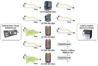 Figure 5. An existing DC strain gauge can be replaced with a higher-performance AC version and seamlessly interface with existing systems by recreating the legacy electrical signal (e.g., 4–20 mA) or digital network interface |
H. Philip White, MS Computer Science, can be reached at ioSelect Inc., San Diego, CA; 877-343-8467, www.ioselect.com.