
Resistance temperature detectors (RTDs) operate on the inherent propensity of metals to exhibit a change in electrical resistance as a result of a change in temperature. We are all aware that metals are conductive materials. It is actually the inverse of a metal's conductivity, or its resistivity, that brought about the development of RTDs. Each metal has a specific and unique resistivity that can be determined experimentally. This resistance, R, is directly proportional to a metal wire's length, L, and inversely proportional to the cross-sectional area, A:
R =ρL/A (1)
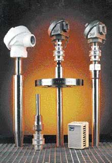 |
| Temperature measurement is essential to a wide variety of industries. This task can be handled by resistance temperature detectors, or RTDs, which are available in a variety of configurations and ratings such as sanitary and explosionproof to satisfy the particular application. |
where:
ρ = the constant of proportionality, or the resistivity of the material
Principle of Operation
RTDs are manufactured from metals whose resistance increases with temperature. Within a limited temperature range, this resistivity increases linearly with temperature:
ρt = ρ0 [1 + a (t t 0 )] (2)
where:
ρt = resistivity at temperature, t
ρ0 = resistivity at a standard temperature, t 0
a = temperature coefficient of resistance (°C 1 )
Combining Equations 1 and 2, setting t 0 to 0°C, and rearranging to the standard linear y = mx + b form, it is clear that resistance vs. temperature is linear with a slope equal to a:
R/R0 = αt + 1 (3)
In theory, any metal could be used to measure temperature. The metal selected should have a high melting point and an ability to withstand the effects of corrosion. Platinum has therefore become the metal of choice for RTDs. Its desirable characteristics include chemical stability, availability in a pure form, and electrical properties that are highly reproducible.
Platinum RTDs are made of either IEC/DIN-grade platinum or reference-grade platinum. The difference lies in the purity of the platinum. The IEC/DIN standard is pure platinum that is intentionally contaminated with other platinum group metals. The reference-grade platinum is made from 99.99% pure platinum. Both probes will read 100 Ω at 0°C, but at 100°C the DIN grade platinum RTD will read 138.5 Ω and the reference grade will read 139.02 Ω. International committees have been established to develop standard curves for RTDs. The committees have defined a mean temperature coefficient to be between 0°C and 100°C. Solving Equation (3) for a:
α = (R 100 R 0 ) / R 0 t (4)
IEC/DIN grade platinum: a = 0.00385 Ω/Ω/°C
reference grade platinum: a = 0.003926 Ω/Ω/°C (max.)
The relationship between resistance and temperature can be approximated by the Callendar-Van Dusen equation:
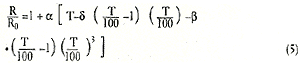
where:
T = temperature (°C)
R = resistance at temperature T
R0 = resistance at the ice point
α = constant (gives the linear approximation to the R vs. T curve)
δ= constant
β= constant (b = 0 when T is >0°C)
The actual values for the coefficients,α, δ, and β are determined by testing the RTD at four temperatures and solving the equations. The Callendar-Van Dusen equation can be simplified to:
Rt = R0 [1 + At + Bt2 + C(t 100°C)]t 3 (6)
In the positive quadrant, temperatures over 0°C, the behavior of a PRT may be described by a quadratic equation in the form:
Rt = R0 (1 + At + Bt2 ) (7)
As written, the above implies that valid equations may be generated from empirical data taken using 0°C plus two arbitrarily selected positive temperatures. For a single PRT, the constants A and B could be slightly different, depending on the temperatures selected.
Callendar resolved the issue by defining two additional fixed points:
- The boiling point of water, 100°C
- The triple point of zinc, 419.58°
The coefficients A, B, and C depend on the wire material (i.e., platinum) and its purity. International standard IEC 751 describes the specifications that permit universal interchangeability among platinum RTDs.
The coefficients for platinum RTDs according to the IEC 751-2 (ITS90) Standard are:
A = 3.9083 × 10³ C1
B = 5.775 × 10⁷ C2
C = 4.183 × 10¹² C3
Fabrication
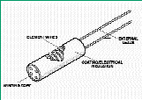
Figure 1. The wire-wound element is built by winding a small-diameter platinum sensing wire around a nonconducting mandrel.
RTD elements take either of two forms: wire wound (see Figure 1) or thin film. Wire-wound elements are made primarily by winding a very fine strand of platinum wire into a coil until there is enough material to equal 100 Ω of resistance. The coil is then inserted into a mandrel and powder is packed around it to prevent the sensor from shorting and to provide vibration resistance. This is a time-consuming method and all work is done manually under a microscope, but the result is a strain-free design.
Thin film elements (see Figure 2) are manufactured by depositing a thin layer of platinum or its alloys on a ceramic substrate. The metal is deposited in a specific pattern and trimmed to the final resistance. The elements are then coated with a glass or epoxy for moisture resistance. An advantage of the thin film sensor is that a greater resistance can be placed in a smaller area; 1000 Ω RTD sensors are readily available. Thin film sensors are susceptible to some strain, however, and have a maximum temperature coefficient of 0.00385 Ω/Ω/°C. On the plus side, 1000 Ω elements offer the advantage of increased resolution per degree of temperature, and errors due to lead wire resistance are minimized. Although thin film elements would appear preferable, most of the older electronics are designed to accept only the 100 Ω sensor.
Specifications
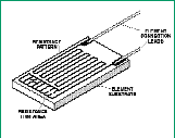
Figure 2. The thin film sensing element is made by depositing a thin layer of platinum in a resistance pattern on a ceramic substrate. A layer of glass or epoxy is applied for moisture protection.
When discussing RTDs, several specifications must be considered:
- Wiring configuration (two-, three-, or four-wire)
- Self-heating
- Accuracy
- Stability
- Repeatability
- Response time
Wiring Configuration. Serious lead wire resistance errors can occur when using a two-wire RTD (see Figure 3A), especially in a 100 Ω sensor. In a two-wire circuit, a current is passed through the sensor. As the temperature of the sensor increases, the resistance increases. This increase in resistance will be detected by an increase in the voltage ( V = I • R). The actual resistance causing the voltage increase is the total resistance of the sensor and the resistance introduced by the lead wires. As long as the lead wire resistance remains constant, it will not affect the temperature measurement. The wire resistance will change with temperature, however, so as the ambient conditions change, the wire resistance will also change, introducing errors. If the wire is very long, this source of error could be significant. Two-wire RTDs are typically used only with very short lead wires, or with a 1000 Ω element.
In a three-wire RTD (see Figure 3B), there are three leads coming from the RTD instead of two. L1 and L3 carry the measuring current, while L2 acts only as a potential lead. Ideally, the resistances of L1 and L3 are perfectly matched and therefore canceled. The resistance in R3 is equal to the resistance of the sensor, Rt , at a given temperature (usually the midpoint of the temperature range). At this point, no current passes through the center lead. As the temperature of the sensor increases, the resistance of the sensor increases, causing the resistance to be out of balance. Current then flows in the center lead and will indicate an offset temperature.
The optimum form of connection for RTDs is a four-wire circuit (see Figure 3C). It removes the error caused by mismatched resistance of the lead wires. A constant current is passed through L1 and L4; L2 and L3 measure the voltage drop across the RTD. With a constant current, the voltage is strictly a function of the resistance and a true measurement is achieved. This design is slightly more expensive than two- or three-wire configurations, but is the best choice when a high degree of accuracy is required.
Self-Heating. To measure resistance, it is necessary to pass a current through the RTD. The resultant voltage drop across the resistor heats the device in an effect known as the I 2 R, or Joule heating. The sensor's indicated temperature is therefore slightly higher than the actual temperature. The amount of self-heating also depends heavily on the medium in which the RTD is immersed. An RTD can self-heat up to 100 3 higher in still air than in moving water.
Accuracy, Stability, and Repeatability. These three terms are often confused, but it is important to understand the difference.
- Accuracy. IEC standard 751 sets two tolerance classes for the accuracy of RTDs: Class A and Class B:
Class A: Δt = ±(0.15 + 0.002 • | t | )
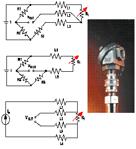 |
| Figure 3. Lead wires have resistance that is a function of the material used, wire size, and lead length. This resistance can add to the measured RTD resistance, and improper wire compensation can result in significant errors. The common configurations of RTDs are two (A), three (B), or four wires (C). |
Class B: Δt = ±(0.30 + 0.005 • | t | )
where:
| t | = absolute value of temperature in °C
Class A applies to temperatures from 200°C to 650°C, and only for RTDs with three- or four-wire configurations. Class B covers the entire range from 200°C to 850°C.
- Stability. This is the sensor's ability to maintain a consistent output when a constant input is applied. Physical or chemical changes can cause calibration drift. The material that the platinum is adhered to, whether wound on a mandrel or on a substrate, can expand and contract, straining the wire. Drift rates conservatively specified by manufacturers are typically 0.05°C/yr.
- Repeatability. Repeatability is the sensor's ability to give the same output or reading under repeated identical conditions.
Absolute accuracy is not necessary in most applications. The focus should be on the stability and repeatability of the sensor. If an RTD in a 100.00°C bath consistently reads 100.06°C, the electronics can easily compensate for this error. The stability of RTDs is exceptional, with most experiencing drift rates of 0.05°C over a five-year period.
Response Time. Response time varies according to the application. It is the sensor's ability to react to a change in temperature, and depends on the sensor's thermal mass and proximity to the material being tested. For instance, an RTD sensor in a thermowell will react more slowly than the same sensor immersed directly into a process. RTD specifications will list the sensor's time constant, which is the time it takes for an RTD to respond to a step change in temperature and come to 63% of its final equilibrium value. Response times are calculated in water flowing at 0.2 m/s and in air flowing at 1 m/s. This gives a useful comparison of RTD sensor configurations.
Summary
Temperature measurement can be very simple or very complex, depending on your application and requirements. Understanding these RTD specifications is an important first step toward finding the right device.